
Add to Cart
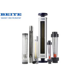
Glass Tube Rotor Flowmeter
Description
The glass tube rotor flowmeter is equipped with a float (rotor)
that can move up and down in a vertical transparent conical tube.
When the liquid passes through the conical tube from the bottom, it
is throttled by the float, creating a differential pressure between
the upstream and downstream of the float. The float moves rises
under the action of this differential pressure. When the force that
causes the float to rise is equal to the combined force of gravity,
float and viscosity force, the float is at the equilibrium
position. Therefore, the fluid flow rate flowing through the flow
meter is equal to the rising height of the float, that is, the same
as the height of the flow meter. There is a certain proportional
relationship between the flow areas, and the position and height of
the float can be used as a flow measurement.
They are mainly composed of tapered glass tubes, floats, upper and
lower bases, upper and lower stops, support plates, outer covers,
sealing rings, etc. For flowmeters with a diameter of less than 10
mm, pipe (soft or hard) connections are used and can be equipped
with There is a flow regulating valve. For flowmeters with
diameters above 15 mm, use flange connection (JB78-59 cast iron
flange).
principle
Features
Better-Smart instrument direct supplier
Accuracy / Transparent glass tube can measure small flow rates of
liquids and gases. The water flow rate is small and can measure
0.4-4ml/min.
one
Wetted materials available / Range ratio A variety of wetted
materials available: aluminum, brass, stainless steel, PP plastic,
PTFE, FEP, etc.
two
Energy / Small pressure loss No external power supply is required,
and the flow indication is clear and intuitive.
three
Switch / Simple structure can have alarm switch output.
Four
Anti-corrosion / Measuring range Can measure corrosive fluids
five
Rich connection forms / Corrosion resistance Various process
connection forms: threads, pagoda joints, ferrules, flanges, etc.
main application
Sanitary metal tube rotor flowmeter has a simple structure,
reliable operation, high accuracy and wide application range.
Atmospheric sampling flow monitoring of water treatment equipment,
gas flow monitoring in VOCs monitoring, and sewage flow measurement
Water treatment industry RO reverse osmosis, pure water flow
measurement, distilled water flow measurement, injection water flow
measurement
Desulfurization and denitrification, ammonia flow measurement, and
urea solution flow measurement in power plants in the electric
power industry
working principle
The rotor material of the rotameter can be made of stainless steel,
aluminum, bronze, etc.
The flow rate is measured based on the height of the metal tube
float in the tapered tube. The pressure difference generated when
the fluid passes through the gap between the float and the tube
wall is used to balance the weight of the float. The greater the
flow rate, the higher the float is held, giving it a The larger
annulus area, that is, the annulus area changes with the flow rate,
so it is generally called the area method. It is mostly used for
the measurement of medium and small flows, and is equipped with an
electric remote transmitter or a gas remote transmitter.
Specification
| DN (mm) | Model | Measuring range | Spinal canal length(m) | Accuracy grade | Allow the liquid state to be measured | |||
| Water 20℃ | Gas | LZB/LZJ | LZB-()F | Temperature(℃) | Pressure | |||
| 20℃,10132SPa | (MPa) | |||||||
| 2 | LZB-2 | 0.4~4ml/min | 6~60ml/min | 160 | 1.5:2.5 | 2.5:4 | -20~+120 | ≤0.4 |
| 0.6~6ml/min | 10~100ml/min | |||||||
| 1.0~10ml/min | 16~160ml/min | |||||||
| 1.6~16ml/min | 25~250ml/min | |||||||
| 3 | LZB-3 | 2.5~25ml/min | 40~400ml/min | |||||
| 4~40ml/min | 60~600ml/min | |||||||
| 6~60ml/min | 100~1000ml/min | |||||||
| 10~100ml/min | 160~1600ml/min | |||||||
| 4 | LZB-4 LZB-4F | (1~10)L/h | (16~160)L/h | |||||
| (1.6~16)L/h | (25~250)L/h | |||||||
| (2.5~25)L/h | (40~400)L/h | |||||||
| 6 | LZB-6 LZJ-6F | (2.5~25)L/h | (40~400)L/h | |||||
| (4~40)L/h | (60~600)L/h | |||||||
| (6~60)L/h | (100~1000)L/h | |||||||
| 10 | LZB-10 LZJ-10F | (6~60)L/h | (100~1000)L/h | 2.5 | ≤0.6 | |||
| (10~100)L/h | (160~1600)L/h | |||||||
| (16~160)L/h | (250~2500)L/h | |||||||
| 15 | LZB-15 LZJ-15F | (16~160)L/h | (0.25~2.5)m³/h | 350 | ||||
| (25~250)L/h | (0.4~4)m³/h | |||||||
| (40~400)L/h | (0.6~6)m³/h | |||||||
| 25 | LZB-25 LZJ-25F | (40~400)L/h | (1~10)m³/h | |||||
| (60~600)L/h | (1.6~16)m³/h | |||||||
| (100~1000)L/h | (2.5~25)m³/h | |||||||
| 40 | LZB-40 LZJ-40F | (160~1600)L/h | (4~40)m³/h | 430 | ||||
| (250~2500)L/h | (6~60)m³/h | |||||||
| 50 | LZB-50 LZJ-50F | (0.4~4)m³/h | (10~100)m³/h | 450 | ||||
| (0.6~6)m³/h | (16~160)m³/h | |||||||
| 80 | LZB-80 LZB-80F | (1~10)m³/h | (50~250)m³/h | 500 | ≤0.4 | |||
| (1.6~16)m³/h | 80~400)m³/h | |||||||
| 100 | LZB-100 LZB-100F | (5~25)m³/h | (120~600)m³/h | |||||
| (8~40)m³/h | (200~1000)m³/h | |||||||
Installation steps of plastic tube rotor flowmeter
1. Clean the welding slag and debris in the pipeline before
installing the flow meter;
2. The installation inclination of the upright part of the
calibration flowmeter perpendicular to the ground shall not exceed
5°. Otherwise, the measurement accuracy will be affected.
3. Position In order to ensure the measurement accuracy of the flow
meter, a straight pipe section of no less than 10xDN should be
added to the inlet end of the flow meter, and a straight pipe
section of no less than 5xDN should be added to the outlet end. The
regulating control valve should be installed at the flow meter
during measurement. downstream.
4. Model If the measured medium is a large pulsating flow or
two-phase flow, a buffer should be installed upstream of the flow
meter to reduce or weaken the pulsation to ensure that the flow of
the medium is single-phase stable. At the same time, it is
recommended to use a damping type flow meter. .
5. Measuring medium When the measuring medium is dirty or contains
magnetically conductive particles, it is recommended to install a
filter or magnetic filter upstream of the flow meter.
6. The installation of the support flow meter should be able to
properly support the vibration of the pipeline or reduce the axial
load of the flow meter. Otherwise, the support of the fixed flow
meter should be added.
7. Maintenance In order to facilitate the maintenance and repair of
the flow meter, the cleaning of the magnetic filter and the regular
maintenance of the user's pipelines, it is recommended to use the
bypass pipeline as shown in the figure.
8. Stability When the flow meter is used for gas measurement, it
should be ensured that the working pressure in the pipeline is not
less than 5 times the pressure loss of the flow meter, so that the
flow meter can operate stably and normally.
9. Before using the electric remote transmission and the flow meter
with alarm limit switch, open the instrument cover and connect the
wires correctly according to the wiring diagram.
10. According to the warning plate on the indicator of the meter,
take out the damping piece that prevents the float from vibrating
during transportation, and then use the meter after restoring it.
11. If the flow meter is turned on, because there is no pressure in
the pipeline or the system has not reached the normal working
pressure of the instrument, slowly open the control valve until the
system is normal before the instrument can be used. Otherwise, it
is easy to cause the pointer to jump or the float to suddenly move.
A rose damaged by impact.
12. User use: When the user uses it, if the density of the measured
fluid is different from that of water, or the parameters and
working status of the measured gas are different from the
manufacturer's regulations, the flow meter indication reading
should be converted. The conversion method is shown in the
appendix.
Manufacturer strength
Smart instrument direct supply manufacturer
The company has complete production and processing equipment. The
electronics workshop has a modern SMT assembly line and a complete
electronic design and development laboratory. The machinery
workshop has multiple precision CNC lathes, ordinary lathes,
processing, fully automatic circumferential seam welding machines,
drilling machines and other equipment. The calibration workshop has
two liquid calibration test lines and a small and medium flow gas
calibration test line to ensure that each product is tested
according to actual conditions. Calibration and verification to
ensure product quality.
FAQ
1. Q: What information need to be provided to choose the suitable
model?
A: Application field, Nominal pressure ,Medium & medium
temperture , Power supply , Output,
Flow range, Accuracy, Connection and other parameters.
2. Q: Are you a trade company or a manufacturer?
A: We are an ISO approved manufacturer specialized in level and
flow measuring instruments.
OEM & ODM service are available. Welcome to visit us in China.
3. Q: What is your MOQ?
A: To start our cooperation, sample order is acceptable.
4. Q: What is your delivery date for the Intelligent Mini Micro
Turbine Fuel Oil Diesel Flow Meter?
A: The delivery date is about 3-15 working days after receipt of
payment.
5. Q: What is your payment terms?
A: We support T/T, PayPal ,Western Union.
For mass production order, it is 30% deposit in advance and 70%
balance before shipment.
6. Q: Do you have a warranty for the Flow Meter?
A: Yes, we have the warranty of 12 months.