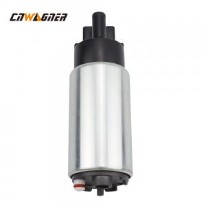
0.35KG Electric Diesel Fuel Pump 23221-50100 Diesel Engine Parts
Brand Name:CNWAGNER
Certification:CE ROHS
Model Number:23221-50100
Minimum Order Quantity:50 pieces/unit
Delivery Time:3-25days
Payment Terms:T/T, Western Union, MoneyGram
Contact Now
Add to Cart
Verified Supplier
Location:
Chongqing Chongqing China
Address:
Room 27-18, Building 1, 118 Daping Street, Chongqing,China
Supplier`s last login times:
within 14 hours
Shipping
lt's easy to get a shipping quote! Just click the button below and complete the short form.
Get Shipping Quote
Product Details
Company Profile
Product Details
Engine Accessories Diesel Engine Parts Electric Engine Fuel Pump 23221-50100
Product Detail
| Products name | Engine Accessories Diesel Engine Parts Electric Engine Fuel Pump |
| Part number | 23221-50100 |
| Size | Standard Size |
| Warranty | 1200hours |
| Sample | Offer |
| Application | Engine Parts |
| Packing | Exported Standard Packing |
| Weight | 0.35KG |
Different types of fuel pump
1.Electric centrifugal booster pump edit voice
In some aircraft, the electric centrifugal booster pump is used as
an auxiliary fuel pump for the fuel system. The motor is usually
installed on the spar corresponding to the lower position of the
fuel tank, and the pump body is immersed in the fuel at the bottom
of the fuel tank. Take sealing measures between the pump impeller
and the motor to prevent fuel or oil vapor from leaking into the
motor. When the fuel enters the pump body, the high-speed rotating
impeller ejects the fuel outward in the radial direction,
generating centrifugal force, increasing the fuel pressure, and
delivering the fuel to the system. The rotating agitation of the
pump also has the function of separating air and oil vapor from the
fuel, so that the fuel supplied to the engine does not contain oil
vapor.
2.Plunger electric fuel pump edit voice
Due to the high cost of electric centrifugal booster pumps, many
small low-wing aircraft fuel systems use electric plunger pumps as
auxiliary fuel pumps for the fuel system. The plunger pump is
usually installed in parallel with the engine-driven diaphragm fuel
pump so that they can supply fuel to the engine individually or
together.
The plunger fuel pump is a pulsation pump, which consists of a
solenoid coil, a plunger, a calibration spring, and two one-way
valves (net 9-14). The electromagnetic coil is wound on the brass
tube connecting the two oil chambers. The elastic force of the
calibration spring pushes the plunger upward, and the
electromagnetic force of the coil pushes the plunger downward. One
one-way valve is installed in the middle of the plunger, and the
other is installed in the middle of the bottom of the brass tube
extension in the oil inlet cavity.
When the plunger pump is not energized, the force of the
calibration spring pushes the plunger up along the brass tube, and
the plunger will attract the magnet and make the contacts contact
through the pivot. After being energized, the current flows through
the electromagnetic wire through the contact to generate
electromagnetic force, which draws the plunger downward into the
coil part. At this time, the fuel in the B cavity flows upward into
the plunger through the one-way valve. When the plunger moves down
to the middle of the solenoid coil, the magnet will no longer be
attracted, the contact will open, and the solenoid coil will be
de-energized. The electromagnetic force disappears. At this time,
the calibration spring pushes up the plunger, and the fuel in the C
cavity is squeezed out and supplied to the engine. At the same
time, the fuel from the fuel tank is pumped into the A cavity, and
then into the B cavity through the bottom one-way valve, ready for
the next fuel supply cycle.
If the engine receives the entire output of the pump, the pump's
pulsation frequency is high; but if the engine carburetor idle
valve is closed, or there is pressure between the carburetor and
the pump, the pump will be in a low-speed pulsation state.
3.Vane fuel pump edit voice
The four steel blades slide along the radial direction of the rotor
in the sliding grooves opened on the rotor. One end of the blade
presses against the inner wall of the pump barrel, and the other
end is in contact with the floating shaft through a spring. The
internal cavity of the rotor is divided into 4 working cavities by
the blade and the floating shaft. The pump barrel is fixed on the
casing of the pump, and there are oil inlet and outlet ports on
both sides. The power of the rotor can be driven by an engine or a
motor.
When the rotor is working, it rotates clockwise. Because the pump
barrel and the rotor are eccentric, the volume of each working
chamber is constantly changing with the rotation of the rotor. The
fuel in the fuel tank is sucked into the working chamber. When the
blades turn to the outlet side, the volume of the working chamber
becomes smaller, and the fuel is squeezed out to flow to the
carburetor.
When the pump outlet pressure is greater than the specified value,
the pressure acting on the lower surface of the pressure relief
valve overcomes the spring force, pushes the pressure relief valve
upwards, and guides the excess fuel from the pump outlet back to
the inlet, so that the fuel supply pipe between the pump outlet and
the carburetor The fuel pressure in the road is always kept within
the specified value. When the vane pump fails during engine
operation, as long as the inlet pressure of the pump is slightly
greater than the outlet pressure, the pressure acting on the
surface of the bypass valve plate overcomes the force of the thin
spring and opens the bypass valve plate downward to make the fuel
full. The flow goes to the carburetor of the engine.
The head of the pump is equipped with a fuel supply pressure
regulating device, which can automatically adjust the fuel pressure
at the pump outlet within the specified range. If the fuel pressure
is abnormal when the pump is working, the pressure regulating
device should be checked first, and the pressure should be
corrected by the adjustment screw test method.
Company shows


0.35KG Electric Diesel Fuel Pump 23221-50100 Diesel Engine Parts
Inquiry Cart
0