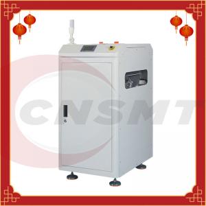
180 Degree PCB Handling Equipment AC 220V 60HZ PCB Inverter Conveyor
Brand Name:CNSMT
Certification:PCB Inverter Conveyor
Model Number:CNSMT-CV300-460
Minimum Order Quantity:1
Delivery Time:3-4days
Payment Terms:L/C, D/A, D/P, T/T, Western Union, MoneyGram
Contact Now
Add to Cart
Site Member
Location:
Shenzhen China
Address:
Fuyong, Baoan ,Shenzhen City,China,
Supplier`s last login times:
within 26 hours
Shipping
lt's easy to get a shipping quote! Just click the button below and complete the short form.
Get Shipping Quote
Product Details
Company Profile
Product Details
180 Degree PCB Handling Equipment AC 220V 60HZ PCB Inverter Conveyor
180Degree PCB Inverter Conveyor-CNSMT
PCB Inverter Conveyor
Product Description
※ The top safety cover can be opened to facilitate the handling of the machine hardware during maintenance
※ Easy to use smart touch screen function control interface
※ Adjustable corner speed to ensure that the PCB board will not slide
※ Stable and balanced width adjustment device (hand control screw adjustment)
※ Small machine footprint
※ Compatible SMEMA interface
Specification
| description | PCB inverter conveyor is used to flip the PCB board to meet the needs of double-sided processing |
| Cycle Time | About 15 seconds |
| power supply | 110-220-230V AC (user specified), single phase |
| Electric load | Maximum 180 VA |
| Air pressure | 0.45-0.6Mpa |
| air flow volume | Up to 30 liters/min |
| Transmission height | 900±20mm (or user specified) |
| Transmission direction | Left→right or right→left (optional) |
Model:
| Model | CNSMT-CV300 | CNSMT-CV350 | CNSMT-CV460 |
| PCB SIZE(L×W)~(L×W) | (50x50)~(450x300) | (50x50)~(450x350) | (50x50)~(450x460) |
| Dimension (L×W×H) | 520x520x900 | 570*570*900 | 650*650*900 |
| Weight | Approx.110kg | 130kg | 160kg |
working principle
The PCB board automatic inverter conveyor is used on the SMT line body of the electronic product. The PCB board flows into the turning machine track, and the track performs 180 turning, the A side PCB board enters, and the B side PCB board exits. The overall frame is matched with right profiles, the surface appearance is 1.5mm sheet metal, the flip drive is driven by a stepper motor + belt, with mechanical limit; the track conveying drive is driven by a 15W AC motor + chain
Background technique:
PCB circuit boards, also known as printed circuit boards, are providers of electrical connections for electronic components. Its design is mainly layout design.
The main advantage of using circuit boards is to greatly reduce wiring and assembly errors, and improve the level of automation and production labor rate.
Due to the increasing integration of PCB boards, the production process requires that both the front and back sides of the PCB boards must be processed and produced.
Most of the existing manual flips are used. The flipping equipment used in some factories has complex structures and high procurement costs.
Packing & Delivery
Certification
Company Information
CNSMT is the leading manufacturer and supplieir for SMT machines
and Solution with over 10 years' experience in China. And we can
also do OEM&ODM for SMT traders, we have vast of sources in SMT
field,even you need used or new SMT equipments or other parts, we
can help you get the best quality and competitive cost machines.
What we can do for you:
※ We have our own factory make SMT equipments and devices
※ We have a professional technich engineer team for produce
machines
※ We can customize variety of SMT machines for you according your requirements
※ We buy and sell used and new SMT equipments all over the world
※ We provide you SMT full line machines and export to worldwide
※ Becoming the most reliable Chinese partner for you.
FAQ
Question: What makes you the best company in China?
Answer: We have been in the SMT line of business for more than 10 years already, giving us a solid experience in the industry.
Question: Are you able to customize my orders according to our preferred application?
Answer: Yes, of course! We can customize orders for our customers. We just need you to send your requirements or preferred application via email. We will reply to you within 24-48 hours from receipt with the best solution we have come up for you.
Question: What is the main advantage of the PCB inverter conveyor?
Answer: The main advantage of a PCB inverter conveyor is that you will have a fully automated SMT assembly that can flip your PCBs without the need of manual handling. This is needed to prevent damage due to human error.
Question: Is it easy to use the PCB inverter conveyor?
Answer: Yes, it is. In fact, most of our machines come with an English manual that will help you understand the machine more in terms of functions and processes. Installation and getting the machine started is also easy. If more information is needed, please do not hesitate to contact us back so that we can assist you
Question: What is your lead time for international orders?
Answer: Our normal lead time for all orders whether it is international or local is 3 working days for processing and 10 working days for transit time. Please take note that the actual number of days would still depend on your exact location. Please let us know your exact location so that we can give you a more precise number of days for the lead time of your orders.
Question: What do you use for packaging?
Answer: Normally, we use a strong box for packing your orders. But if the machine requires more protection, we will add wooden crate. You can also let us know your preferred packaging.
Question: Will you require a down payment for customized machines?
Answer: Yes. For customized machines, we will require 70% down payment. 30% is to be paid once the machine is ready for shipment.
Our Service
1,SMT full line solution
2,SMT Peripheral equipments manufacturer
3,SMT feeder, smt nozzle, smt feeder calibration, PCB trolley, feeder trolley, PCB strorage, SMT squeegee manufacturer
4,Buy and sell used and new YAMAHA JUKI FUJI PANASONIC SAMSUNG and reflow oven printers
5,
CNSMT is a leader and a trusted supplier of all PCB machines here in China. We also have a high satisfaction rate from all of our international clients for we are dedicated in providing only the top-quality products for all of your SMT needs.
We have a large stock of all SMT machines, and one of the fastest selling PCB machines that we have is the PCB inverter conveyor. If you are looking for a good quality PCB inverter conveyor, look no more, because we have all kinds of it ready for delivery. If you are not sure what to order, allow us to help you!
Why Choose CNSMT?
- We have high satisfaction rate from all of our customers both in the local and international market.
- We have more than 10 years solid experience when it comes to handling, understanding, and navigating SMT machines.
- We process orders fast and efficiently, so that our customers don’t have to waste time in waiting for their orders.
- Our products are of top quality, for we only partner with reliable manufacturers from well known countries like Japan.
- We always customize orders to make it suitable for everyone’s needs.
- We offer the most competitive rate to all of our customers, so they can save from all of their orders.
These are the reasons why you should only trust CNSMT. We are here to help you find the most effective and most affordable solutions to all of your SMT needs.
If you are looking for a PCB inverter conveyor, please see the details below.
What is a PCB Inverter Conveyor?
A PCB inverter conveyor or also known as the PCB flip conveyor, is what you use if you want to eliminate the need of manual handling the PCBs when flipping it on either side for processing.
Eliminating manual handling is needed, if you want to avoid the risk of damage and contamination during the process. The PCB inverter conveyor comes in many forms and features. But mostly, the general goal of it is to be able to flip the board on one side to process it, and then do it on the other side. This process is automated, without the need of human intervention.
Automation Is The Key To High Productivity
We all know that automation is going to bring a lot of benefits to an SMT line of assembly. SMT factories / companies should consider this if they want to:
- Achieve continuous work with uniform results.
- Lower manpower cost
- Lower risk of damage due to human error
- High productivity
- Achieve a modern state of SMT assembly.
Features of A PCB Inverter Conveyor
As mentioned, a PCB inverter conveyor comes in various models, features, and functionalities. But just to name a few common features you will find in most PCB inverter conveyors, see the information below:
- Has an easy to use touchscreen control system.
- Equipped with a By-pass mode
- Can flip PCB in 180 degrees
- PCL control
- Equipped with optical sensors for efficient control of the entire process from start to finish.
- SMEMA compliant and CE certified
Technical realization elements:
Based on this, the utility model provides a PCB board flipping/inverter conveyor machine which can automatically flip the PCB board and has a simple structure and low cost.
In order to achieve the purpose of the utility model, the utility model adopts the following technical solutions:
A PCB board turning machine, which includes:
The frame has a first end and a second end;
The roller set is arranged on the frame close to the first end;
The conveying mechanism is arranged on the frame; the conveying mechanism includes a first rotating shaft, a second rotating shaft, a first motor, and a plurality of mutually spaced conveyor belts.
The first rotating shaft is located on the frame close to the first end Position, the second rotating shaft is located on the frame close to the second end, and a number of the conveyor belts are driven by the first rotating shaft and the second rotating shaft;
The flipping mechanism is arranged on the frame; the flipping mechanism includes a rotating shaft, a first clamping strip group, a second clamping strip group, a third clamping strip group, a fourth clamping strip group, and a sensor, and the rotation shaft Located in the middle of the frame, the first clamping strip group and the second clamping strip group, the third clamping strip group and the fourth clamping strip group are respectively located on both sides of the rotating shaft and connected to the rotating shaft.
A clip bar group and a third clip bar group are located on the same side of the rotating shaft, and the second clip bar group and the fourth clip bar group are located on the same side of the rotating shaft.
In some of the embodiments, the first clamping strip group includes a plurality of first clamping strips arranged at intervals, and the third clamping strip group includes a plurality of third clamping strips arranged at intervals, and each first clamping strip corresponds to a first clamping strip. Three clamping bars,
the first clamping bar and the third clamping bar have an angle of 15-40 degrees; the second clamping bar group and the fourth clamping bar group are located on the same side of the rotating shaft,
the The second clip bar group includes a plurality of second clip bars arranged at intervals, and the fourth clip bar group includes a plurality of fourth clip bars arranged at intervals, and each second clip bar corresponds to a fourth clip bar. There is an angle of 15-40 degrees between the strip and the fourth clamping strip; the third clamping strip and the fourth clamping strip are located between two adjacent conveyor belts and are located lower than the conveyor belt;
The sensor is arranged on the side of the conveyor belt.
In some of the embodiments, the transfer mechanism has two sets, and the rotating shaft of the flap mechanism is located between the two sets of transfer mechanisms.
In some of the embodiments, at least two sensors are provided on each transmission mechanism.
In some of the embodiments, the distance between the conveyor belt and the roller set is less than the size of the smallest side of a PCB board.
In some of the embodiments, there is an angle of 25 degrees between the first clip bar and the third clip bar and between the second clip bar and the fourth clip bar.
The PCB board turning machine of the utility model is provided with a roller group, a conveying mechanism and a plate turning mechanism on the frame.
The roller group sends the PCB board to the conveying mechanism, and the conveying mechanism sends the PCB board to the plate turning mechanism. Between the two clamping strips, the flipping mechanism operates to flip the PCB board to the other side, thereby processing the other side of the PCB;
the flipping mechanism is composed of a rotating shaft and a number of clamping strips set up and down, and its structure is simple and costly low.
Description of the drawings
Figure 1 is a schematic diagram of the overall structure of a PCB board flipping machine according to a preferred embodiment of the present invention;
2 is a schematic diagram of the structure of the flipping mechanism of the PCB flipping machine described in FIG. 1;
FIG. 3 is a schematic top view of the structure of the PCB board turning machine described in FIG. 1.
Detailed ways
In order to facilitate the understanding of the present utility model, the present utility model will be described in a more comprehensive manner with reference to the relevant drawings. The preferred embodiments of the present invention are shown in the drawings. However, the present invention can be implemented in many different forms and is not limited to the embodiments described herein.
On the contrary, the purpose of providing these embodiments is to make the understanding of the disclosure of the present utility model more thorough and comprehensive.
It should be noted that when an element is referred to as being "fixed to" another element, it can be directly on the other element or a central element may also be present. When an element is considered to be "connected" to another element, it can be directly connected to the other element or an intermediate element may be present at the same time.
Unless otherwise defined, all technical and scientific terms used herein have the same meaning as commonly understood by those skilled in the technical field of the present utility model. The terminology used in the description of the present utility model herein is only for the purpose of describing specific embodiments, and is not intended to limit the present utility model.
Please refer to FIGS. 1 to 3, the PCB board flipping machine 100 of the present invention flips the PCB board. The flipping machine 100 includes a frame 10, a roller set 20, a transfer mechanism 30, and a flipping mechanism 40.
The roll set 20, the transfer mechanism 30 and the flipping mechanism 40 are all located on the frame 10, and the roll set 20 is used for connecting flips. With the machine 100 and other PCB board processing equipment, the transfer mechanism 30 is used to transfer the PCB board, and the flipping mechanism 40 is used to flip the PCB board.
Please refer to FIG. 1, the rack 10 has a first end 11 and a second end 12. The roller set 20 is arranged on the frame 10 close to the first end 11, and is used to send the PCB board processed by the front equipment to the conveying mechanism 30. In this embodiment, the roller set 20 includes several rollers.
1 and 3, the transmission mechanism 30 is set on the frame 10 and moves along the top surface of the frame 10. The conveying mechanism 30 includes a first rotating shaft 31, a second rotating shaft 32, a first motor (not shown), and a number of mutually spaced conveyor belts 33. The first rotating shaft 31 is located on the frame 10 close to the first end 11, and the second rotating shaft 32 is located on the frame 10 close to the second end 12, the conveyor belt 33 is wound around the first rotating shaft 31 and the second rotating shaft 32, and the conveyor belt 33 is driven by the first rotating shaft 31 and the second rotating shaft 32.
In this embodiment, the distance between the conveyor belt 33 and the roller set 20 is smaller than the size of the smallest side of a PCB board, so as to prevent the PCB board from falling during the process of being transported by the roller set 20 to the conveyor belt 33.
1 and 2, the turning mechanism 40 is set on the frame 10, and includes a rotating shaft 41 arranged in the middle of the frame 10, a first clamping strip group 42, a second clamping strip group 43, and a first clamping strip group 42 connected to the rotation shaft 41. The three clamping bar group 44, the fourth clamping bar group 45 and the sensor 46, the first clamping bar group 42 and the third clamping bar group 44 correspond to each other and are located on the same side of the shaft 41,
the second clamping bar group 43 and the fourth clip The strip groups 45 correspond to and are respectively located on the same side of the rotating shaft 41.
The first clamping bar group 42 includes a plurality of first clamping bars 421 arranged at intervals, the third clamping bar group 44 includes a plurality of third clamping bars 441 arranged at intervals, and each first clamping bar 421 corresponds to a third clamping bar 441, There is an angle of 15-40 degrees between the first clamping bar 421 and the third clamping bar 441, so that the PCB board can be inserted between the first clamping bar 421 and the third clamping bar 441.
In this embodiment, the angle The second clamping strip group 43 includes a plurality of second clamping strips 431 arranged at intervals, and the fourth clamping strip group 45 includes a plurality of fourth clamping strips 451 arranged at intervals, and each second clamping strip 431 corresponds to a fourth The clamping bar 451, the second clamping bar 431 and the fourth clamping bar 451 have an angle of 15-40 degrees, so that the PCB board can be inserted between the second clamping bar 431 and the fourth clamping bar 451. In this embodiment In the example, the angle is 25 degrees.
The third clamping strip 441 and the fourth clamping strip 451 are both located between the two adjacent conveyor belts 33, and the position is lower than the conveyor belt 33.
The conveyor belt 33 automatically enters when the PCB board is transported to the first end 11 of the rack 10 Between the first clamping bar 421 and the third clamping bar 441, the sensor 46 on the rack 10 senses that the PCB board enters the first clamping bar 421 and the third clamping bar 441, and controls the rotation of the shaft 41 to drive the first clamping bar. The strip 421 and the third clamping strip 441 are turned over to the second end 12 of the rack 10 and stop at the corresponding position.
The PCB board falls on the conveyor belt 33 at the second end 12 of the rack 10 and continues to be transported. At this time, the second clamping strip 431 and the fourth The clamping bar 451 is turned over to the first end 11 of the rack 10, and the next batch of PCB boards enters between the second clamping bar 431 and the fourth clamping bar 451, and continues to be turned over, so that the turning of the PCB board can be realized.
In this embodiment, the transmission mechanism 30 has two groups, and the rotating shaft 41 of the plate turning mechanism 40 is located between the two groups of transmission mechanisms 30. At least two sensors 46 are provided on each transmission mechanism 30. In addition, the sensor 46 is arranged on the side of the conveyor belt 33 on the frame 10 to facilitate the sensing of the PCB board without affecting the operation of the plate turning mechanism 40.
The above-mentioned embodiments only express several implementation modes of the present utility model, and their description is relatively specific and detailed, but they should not be understood as a limitation on the scope of the present utility model. It should be pointed out that for those of ordinary skill in the art, without departing from the concept of the utility model, several modifications and improvements can be made, and these all fall within the protection scope of the utility model. Therefore, the scope of protection of the utility model patent should be subject to the appended claims.
To know more about our PCB inverter conveyor, please contact us directly so that we can assist you further with all of your concerns. In the mean time, you may check the information below that will show the most commonly asked questions by our past customers together with the answers.
These are the different questions we have received from our past customers for the PCB inverter conveyor. If you cannot find the exact information above, please contact us directly so that we can answer it for you.
Here at CNSMT, we assure you that you are good hands when it comes to your SMT needs.


180 Degree PCB Handling Equipment AC 220V 60HZ PCB Inverter Conveyor
Inquiry Cart
0