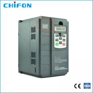
Customized Motor Inverter Input 220v Output 380v 4kw Single To 3 Phase Inverter
Brand Name:CHIFON
Certification:CE, ISO9001, SGS, EAC
Model Number:FPR500Z-4.0G-T4
Minimum Order Quantity:1pcs
Delivery Time:sample order 2 working days, bulk order 7-10 working days
Payment Terms:L/C, T/T, Paypal
Contact Now
Add to Cart
Active Member
Location:
Hangzhou Zhejiang China
Address:
No. 25 Xianxing Rd, Xianlin Industrial Park, Hangzhou, Zhejiang, China
Supplier`s last login times:
within 26 hours
Product Details
Company Profile
Product Details
FPR500E High-performance Synchronous Motor Inverter
►Power class
Single-phase 220v±15% 0.4-2.2kw
Three-phase 380V±15% 0.75-315kw
►Products Specifications:
| Basic Function | Specification | |
| Maximum output frequency | 0~500Hz | |
| Carrier frequency | 0.5kHz~16.0kHz;According to the load characteristics, carrier frequency can be adjusted automatically | |
| Input frequency | Range :47~63Hz | |
| Control mode | V/F Open/closed loop vector control(SVC/FVC) | |
| Speed range | 1:50(Vector mode 0 ) 1Hz/150% rated torque | |
| Overload capability | G type:150% rated current for 60s; 180% rated current for 3s P type:120% rated current for 60s; 150% rated current for 3s | |
| Torque boost | Auto Torque boost Manual Torque boost; 0.1%~30.0%. | |
| V/F curve V/F | Four modes : Line , Multi-point , Square V/F curve, V/F separation | |
| Jog control | Jog frequency range:0.00Hz to F0-10(Max frequency) | |
| Accelerate/Decelerate curve | Line or S-curve Acc/Dec mode, four kinds of Acc/Dec time Range of Acc/Dec Time0.0~65000.00s. | |
| DC brake | DC brake frequency: 0.00Hz to Maximum frequency brake time: 0.0 to 36.0s brake current value: 0.0 to 100% | |
| Simple PLC, Multi-speed | 16-speed operating through built-in PLC or control terminal | |
| Built-in PID | Close loop control system can be formed easily by using PID | |
| Automatic voltage regulating (AVR) | Output voltage is regulated when voltage of the power network changes | |
| Overvoltage and over current stall control | During operation automatically limits the inverter output current and bus voltage, to prevent fan over current and overvoltage trip. | |
| Rapid current limiting function | Minimizing flow failures, protect the normal operation of the inverter | |
| Instantaneous stop non-stop | Load feedback energy compensation voltage is reduced and continues to maintain a short time when change is momentarily interrupted. | |
| Speed tracking start | For high-speed rotation of the motor speed identification, impact- free smooth start | |
| Rapid current limit | Rapid software and hardware limiting technology to avoid frequent converter over current fault. | |
| Virtual IO | Five sets of virtual DO, five sets of virtual DI, enables easy logic control. | |
| Timing Control | Timing control: set the time range 0.0Min~6500.0Hour | |
| Multi-motor switch | Two independent motor parameters, enabling two motors switching control | |
| Bus Support | Two independent Modbus communication, CAN-Link | |
| Command source | Given the control panel, control terminal, serial communication
port given. It can be switched by a variety of ways. | |
| Torque boost | Auto Torque boost Manual Torque boost ; 0.1%~30.0%. | |
| Frequency source | Nine kinds of frequency sources: digital setting, analog voltage setting, analog current setting, pulse setting, or serial port and so on. It can be switched by a variety of ways. | |
| Auxiliary frequency source | Nine kinds of auxiliary frequency source. Flexible implementation
of auxiliary frequency tuning, frequency synthesis. | |
| Input terminal | Six digital input terminals, one only supports 50khz high pulse
input Two analog input terminals, one support 0V~10V voltage input One support 0 ~ 10V voltage input or 0 ~ 20mA current input | |
| Output terminal | One high-speed pulse output terminal (optional open collector
type), support of square wave 0 ~ 50kHz signal output One digital output terminal One relay output terminals Two analog output terminals, support 0 ~ 20mA current output or 0 ~ 10V voltage output | |
| Display and operation | ||
| LED display | Display parameters and status information | |
| The key lock and function selection | Achieve some or all of the keys locked, scope definition section
keys to prevent misuse. | |
| Protection function | Input/output phase failure protection ,Overcurrent protection ;Over voltage protection; Undervoltage protection; Overheat protection ; Overload protection | |
| Options | Brake assembly, PG card | |
| Environment | ||
| Application environment | In-door, free from direct sunlight, dust , corrosive gas, combustible gas, oil mist , steam , water drop and salt . | |
| Altitude | Lower than 1000m | |
| Vibration | Less than 5.9m/s(0.6g) | |
►Product introduction
Energy Savings with Variable Speed Drives
If you have an AC motor-driven application that does not need to be run at full speed, then you can cut down energy costs by controlling the motor with a Variable Speed Drive (VSD). Variable Speed Drives (Also known as Variable Frequency Drives) allow you to match the speed of the motor-driven equipment to the process requirement.
Variable Torque Versus Constant Torque
Variable speed drives, and the loads they are applied to, can generally be divided into two groups: constant torque and variable torque. The energy savings potential of variable torque applications is much greater than that of constant torque applications. Variable torque loads include centrifugal pumps and fans, which make up the majority of HVAC applications. Constant torque loads include vibrating conveyors, punch presses, rock crushers, machine tools, and other applications where the drive follows a constant V/Hz ratio.
Why Variable Torque Loads Offer Great Energy Savings
In variable torque applications, the torque required varies roughly with the square of the speed, and the horsepower required varies approximately with the cube of the speed, resulting in a large reduction of horsepower for even a small reduction in speed. A motor in a variable torque application will consume only 25% as much energy at 50% speed as it will at 100% speed. This is referred to as the Affinity Laws, which define the relationships between speed, flow, torque, and horsepower.
Energy Consumption
Variable Speed Drives (VSDs) allow you to consume less energy than other speed control techniques when load requirements are less than full speed, as is usually the case in HVAC applications.
Extended Equipment Life and Reduced Maintenance
Single-speed starting methods start motors abruptly, subjecting the motor to a high starting torque and to current surges that are up to 10 times the full-load current. Variable speed drives, on the other hand, gradually ramp the motor up to operating speed to lessen mechanical and electrical stress, reducing maintenance and repair costs, and extending the life of the motor and the driven equipment.
Soft starts, or reduced-voltage soft starters (RVSS), are also able to step a motor up gradually, but drives can be programmed to ramp up the motor much more gradually and smoothly and can operate the motor at less than full speed to decrease wear and tear. Variable speed drives can also run a motor in specialized patterns to further minimize mechanical and electrical stress. For example, an S-curve pattern can be applied to a conveyor application for smoother decel/accel control, which reduces the backlash that can occur when a conveyor is accelerating or decelerating.
Problems Caused by Full-Voltage Starters
At the instant of energization, the locked rotor (zero-speed) is about 600% of full-load running current This heavy current then drops off gradually as the load breaks loose, and the motor comes up to speed, but causes unacceptable voltage sag on the power system, adversely affecting other loads. It can also cause shock damage and long-term excessive wear on the motor. Using this starting method may force the utility to impose a limit on the size of motors you can use, since across-the-line starting causes problems upstream into the utility's system, creating problems for other customers. The switching surges of abruptly starting and stopping create stress on the motor insulation.
Certificates
►Product Application


Customized Motor Inverter Input 220v Output 380v 4kw Single To 3 Phase Inverter
Inquiry Cart
0