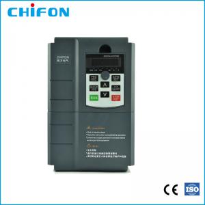
Air Compressor AC Drive Variable Frequency Drive Inverter 220V 380V 7.5 KW VFD
Brand Name:CHIFON
Certification:CE,ISO,SGS,EAC
Model Number:FPR500A-7.5G/11P-T4
Minimum Order Quantity:1pcs
Delivery Time:sample order 2 working days, bulk order 7-10 working days
Payment Terms:L/C, T/T, Paypal
Contact Now
Add to Cart
Active Member
Location:
Hangzhou Zhejiang China
Address:
No. 25 Xianxing Rd, Xianlin Industrial Park, Hangzhou, Zhejiang, China
Supplier`s last login times:
within 26 hours
Product Details
Company Profile
Product Details
Air Compressor AC Drive VFD 220V 380V 7.5KW Variable Frequency Inverter
FPR High-performance closed-loop vector converter
Product introduction
FPR500 series relies on TI company's DSP dual-core professional
control motor chip, which supplies the international leading vector
control algorithm to realize the real high-precision flux vector
torque control. It has built-in pg vector control (VC), pg-free
vector control (SVC), and V/F control modes, which are widely applied to high-speed control accuracy, rapid torque
response, and high performance at low frequency. The integration of torque control, speed control, and position
control can meet the high-performance requirements of customer
applications. And, FPR 500 has the ability to exceed the anti-trip performance of
similar products and adapt to the severe power grid, ambient
temperature, humidity, and dust, greatly improving the reliability of products.
Technical characteristics
Drive motor type:Ac asynchronous motor, Ac permanent magnet synchronous motor
Four control modes:PG vector control(FVC), PG-free vector control(SVC),
V / F control, Torque control
Speed control range:PG vector control(FVC)1:1000
PG- free vector control(SVC)1:200
V / F control 1:50
Speed control accuracy:PG vector control (FVC)±0.2%
PG- free vector control (SVC)±0.5%
Starting torque:PG vector control(FVC):180 % rated torque/0.01Hz
PG- free vector control (SVC)150% rated torque/0.25Hz
Torque control accuracy:PG vector control (FVC)±5%
PG- free vector control (SVC)±8%
Multi-motor switching: Two groups of motor parameters can realize the switching control of
the two motors.
Motor overheating protection:Optional IO expansion card, analog A / 3 can accept input from the
motor temperature sensor
Supports multiple encoders:Supports differential, open collector, uvw, rotary transformer,
sine and cosine encoder
Torque limitation and control: the "excavator" feature, automatically limits the torque during
operation to prevent frequent overcurrent trips. Closed-loop mode
can realize torque control.
Products Specifications:
| Basic Function | Specification | |
| Maximum output frequency | 0~500Hz | |
| Carrier frequency | 0.5kHz~16.0kHz;According to the load characteristics, carrier frequency can be adjusted automatically | |
| Input frequency | Range :47~63Hz | |
| Control mode | V/F Open/closed loop vector control(SVC/FVC) | |
| Speed range | 1:50(Vector mode 0 ) 1Hz/150% rated torque | |
| Overload capability | G type:150% rated current for 60s; 180% rated current for 3s 150% rated current for 3s | |
| Torque boost | Auto Torque boost Manual Torque boost; 0.1%~30.0%. | |
| V/F curve V/F | Four modes : Line , Multi-point , Square V/F curve, V/F separation | |
| Jog control | Jog frequency range:0.00Hz to F0-10(Max frequency) | |
| Accelerate/Decelerate curve | Line or S-curve Acc/Dec mode, four kinds of Acc/Dec time Range of Acc/Dec Time0.0~65000.00s. | |
| DC brake | DC brake frequency: 0.00Hz to Maximum frequency brake time: 0.0 to 36.0s brake current value: 0.0 to 100% | |
| Simple PLC, Multi-speed | 16-speed operating through built-in PLC or control terminal | |
| Built-in PID | Close loop control system can be formed easily by using PID | |
| Automatic voltage regulating (AVR) | Output voltage is regulated when voltage of the power network changes | |
| Overvoltage and over current stall control | During operation automatically limits the inverter output current and bus voltage, to prevent fan over current and overvoltage trip. | |
| Rapid current limiting function | Minimizing flow failures, protect the normal operation of the inverter | |
| Instantaneous stop non-stop | Load feedback energy compensation voltage is reduced and continues to maintain a short time when change is momentarily interrupted. | |
| Speed tracking start | For high-speed rotation of the motor speed identification, impact- free smooth start | |
| Rapid current limit | Rapid software and hardware limiting technology to avoid frequent converter over current fault. | |
| Virtual IO | Five sets of virtual DO, five sets of virtual DI, enables easy logic control. | |
| Timing Control | Timing control: set the time range 0.0Min~6500.0Hour | |
| Multi-motor switch | Two independent motor parameters, enabling two motors switching control | |
| Bus Support | Two independent Modbus communication, CAN-Link | |
| Command source | Given the control panel, control terminal, serial communication
port given. It can be switched by a variety of ways. | |
| Torque boost | Auto Torque boost Manual Torque boost ; 0.1%~30.0%. | |
| Frequency source | Nine kinds of frequency sources: digital setting, analog voltage setting, analog current setting, pulse setting, or serial port and so on. It can be switched by a variety of ways. | |
| Auxiliary frequency source | Nine kinds of auxiliary frequency source. Flexible implementation
of auxiliary frequency tuning, frequency synthesis. | |
| Input terminal | Six digital input terminals, one only supports 50khz high pulse
input Two analog input terminals, one support 0V~10V voltage input One support 0 ~ 10V voltage input or 0 ~ 20mA current input | |
| Output terminal | One high-speed pulse output terminal (optional open collector
type), support of square wave 0 ~ 50kHz signal output One digital output terminal One relay output terminals Two analog output terminals, support 0 ~ 20mA current output or 0 ~ 10V voltage output | |
| Display and operation | ||
| LED display | Display parameters and status information | |
The key lock and function selection | Achieve some or all of the keys locked, scope definition section
keys to prevent misuse. | |
| Protection function | Input/output phase failure protection ,Overcurrent protection ;Over voltage protection; Undervoltage protection; Overheat protection ; Overload protection | |
| Options | Brake assembly, PG card | |
| Environment | ||
| Application environment | In-door, free from direct sunlight, dust , corrosive gas, combustible gas, oil mist , steam , water drop and salt . | |
| Altitude | Lower than 1000m | |
| Vibration | Less than 5.9m/s(0.6g) | |
Technical Artical:
Variable frequency drive (VFD) advances enable users to do more with less.
The demand for efficient motor controls due to rising energy prices and a trend toward energy efficiency has resulted in a growing demand for variable frequency drives (VFDs). The market for VFDs is expected to increase at a rate of 5.94% (CAGR) in the next three years, so it’s not surprising manufacturers are investing in state-of-the-art VFD technology.
The latest advances in VFD software and hardware tackle common problems original equipment manufacturers (OEMs), system integrators, and manufacturers have been wrestling with for years: enabling teams to do more—faster and easier—with fewer resources.
1. Wireless diagnostics
Wireless diagnostics represent the future of VFDs whether it’s Wi-Fi, Bluetooth, or something else entirely. In a typical plant where access to a drive in a closed enclosure may be limited, engineers can connect directly to the system from a distance using the wireless signal built into the drive.
Online software enables engineers to view and diagnose problems without touching the drive or its enclosure.
2. Flexible integration
VFDs with flexible integration allow engineers to solve for the application challenge once and then interface to an upper-level programmable logic controller (PLC) of choice.
For example, say an OEM is selling a given machine to customers both domestically and abroad. Regional trends in PLC preference are not an obstacle for machine integration. The OEM can take a drive with multiple communication options, solve the machine application once, and pick the option that matches the upper-level controller choice for each customer.
VFDs constructed specifically for flexible integration usually consist of a single basic inverter with control or networking modules that can be selected at will.
3. Modular memory
Gone are the days when technicians would have to go into the keypad to program a replacement VFD. Soon, having to use a PC or even just a USB stick to transfer the configuration to a replacement drive will be a thing of the past.
Today, drives with removable, modular, nonvolatile memory make maintenance quick and easy. They eliminate the need to connect additional hardware. If a piece goes bad, device replacement is as simple as taking the memory module out of the old drive and putting it into a new one.
4. Predictive maintenance
Manufacturers are gathering massive amounts of data from their machinery and manipulating it into business intelligence that drives predictive maintenance.
The Internet of Things (IoT), a global trend in every industry, has had an impact on VFDs by speeding and simplifying the flow of information from machine to technician and back again. As such, manufacturers are making changes to everything from their machines to their information technology (IT) departments to facilitate the collection, analysis, and application of drive data.
From a hardware perspective, teams are moving away from serial and toward Ethernet as the network of choice. Basic IT departments are familiar with Ethernet switches, hubs, and routers, resulting in a more seamless integration when it comes to data transfer.
Complex communication strategies are requiring modern VFDs to report lifetime counters, production rates, downtimes, power output, and more for better real-time decision making.


Air Compressor AC Drive Variable Frequency Drive Inverter 220V 380V 7.5 KW VFD
Inquiry Cart
0