
Add to Cart
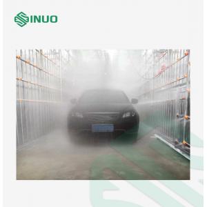
Customizable Rain Environment Simulation Test Room For Electric Vehicles
Product Overview
1. System Purpose
1.1 The test purpose of this test system is mainly to test the product under the condition of rain, the ability of the product to prevent the penetration of rainwater and the rainproof performance during or after the rain.
1.2 To check whether the assembly of the vehicle body, doors, windows and sunroof is normal, whether the sealing performance is reliable, and whether the installation method is correct
1.3 This test system is mainly used for the rainproof sealing performance of various types of passenger cars, vans, etc.
2. Applied Standards
QC/T 476—2007 Rain proof performance limit and test method for bus
QC/T 450—2010 Technical Conditions and Test Methods for Insulated Vehicles and Refrigerated Vehicles
QC/T 453-2009 Van Transporter
The rain test is carried out in a special rain room. The rainfall intensity is 5-12mm/min, and the direction is at an angle of 0-45 degrees from the vertical.
3. Designed Parameter
3.1. System function: It is used for the rain test of vehicle sealing performance. Appropriate to the dimensions of the vehicle
| Vehicle Type | Length | Width | Height |
| RV | 5745 | 2098 | 2650 |
| Car | 3395 | 1475 | 1710 |
| Fire Truck | 6750 | 1970 | 2900 |
3.2. Rain intensity: the average of the front part is 7-12±1mm/min, and the average of the two sides, upper, lower and rear is 5-8±1mm/min. The rain intensity of each part can be adjusted manually and displayed on the control panel.
3.3. Power supply: AC three-phase five-wire 380V±5% 50Hz
3.4. Nozzle injection pressure: 275kPa±10kPa
3.5. Pressure gauge: Install a pressure gauge at the outlet of the water pump, pressure: 0~0.5MPa.
3.6. Flowmeter: A flowmeter is installed behind the outlet flow regulating valve of the water pump, the total flow: 0~150m3/h, and six sets of electromagnetic flowmeters are added to the branch pipes to display the flow of each surface.
3.7. Raining time: 1~60min.
3.8. The outer dimension of the spray bracket of the rain test room (length × width × height): about ~11000 × 4000 × 4500mm.
3.9. The frame of the rain test room adopts the drive-in and reverse-out type system body design, leaving a door hole for vehicles to enter and exit, but no door is installed. The size of the system body is designed according to a 6-meter fire truck, and the frame is made of hot-dip galvanized square pipe. The inner wall of the wall is made of stainless steel 304, the thickness is 0.426mm, the outer wall is made of gray-white color steel plate, the thickness is 0.426mm, the left and right sides of the wall are added with two observation windows of 1800*1200mm each, and the frame is made of hot-dip galvanized square tube as a support frame.
Introduction of Structure Features
4. Structure Requirements
4.1. Based on the principles of advanced reliability, economy and practicality, fully consider the characteristics of the product, actively adopt advanced and mature technology and equipment, improve the water seal detection ability of the workpiece, make this index meet the specified technical requirements, and enhance the adaptability of product testing. At the same time, we also take into account the maintenance proximity and convenience of the equipment.
4.2. Our design achieves a reasonable layout, smooth logistics, and pays attention to energy-saving measures for equipment and rational use of energy.
4.3. This test system implements the national policies and regulations on environmental protection, labor safety and health, and the entire project meets the national emission standards and industrial hygiene standards.
4.4. The selection of equipment and materials is mainly domestic, so as to achieve the purpose of being economical, reasonable, reliable and advanced.
4.5. Main layout requirements:
It can be adapted to various models. The top of the spray pipe structure can be adjusted up and down, the left and right front are fixed, and the rear is a flip translation type. The spray pipes and water pipes in the rain room are all made of stainless steel. It can ensure that all kinds of vehicles can drive through it by themselves.
For these nine oblique angles, according to the conventional test standard, the parallel angle rain test is more than 3H, and the remaining angles are usually sprayed for 10 minutes, and each state is repeated 5 times. This can be set by the program (the water spraying time of each state and the number of water spraying cycles in each state). On the touch screen, the test programs of each enterprise can also be edited and saved, so that the test can be called next time.
5. System Description, Performance and Parameters
5.1 Rain Shower Device
Rain shower device mainly include: water pump, automatic pressure regulating valve, water pressure gauge (or water pressure sensor), main pipeline, branch pipeline, electromagnetic flowmeter, pressure sensor, flow regulating valve, nozzle, nozzle pipe rack, nozzle pipe rack moving system, electronic control system, etc.
5.1.1 The average rain intensity at the front of the vehicle body is (12±1) mm/min, and the average rain intensity at the side, rear, top and bottom of the vehicle body is (8±1) mm/min. The intensity of rain can be adjusted by adjusting the valve.
5.1.2 The water supply pressure setting of the water pump needs to ensure that the water outlet pressure of the nozzle is 150kPa±10kPa. The number of pumps configured, head, flow and pipe diameter should meet the requirements of the system. Each spray surface should cover the models with the largest dimensions involved in the rain test, as well as various inspected parts of various models, and the length of the front, middle and rear sections of the rain shower to adapt to changes in vehicle shape and size.
5.1.3 The rain shower device should ensure that water is sprayed on the vehicle from the front, rear, bottom, side and top directions to avoid dead corners of the water spray, and ensure that the pressure and flow of the water spray correspond to each part of the vehicle to meet the standards: QC/T 476-2007 requirements.
5.1.4 The frame structure of the rain shower pipeline is simple and beautiful while ensuring anti-rust and shock-proof.
5.2 Sprinkler System
Pipeline material: The main pipe adopts stainless steel pipe, the branch pipe adopts stainless steel pipe, the control valve adopts butterfly valve, and the pipeline is equipped with pressure gauge and flow meter. Ensure that the equipment operates normally. The branch pipes are evenly arranged to ensure even rainfall in the rain shower.
5.3 Rain Equipment
It is mainly composed of water pump and its driving motor, pressure regulating valve, throttle valve, shut-off valve, pressure gauge, flowmeter, water pipeline accessories, nozzle, reservoir, bracket and nozzle frame drive regulating device.
5.3.1 A pressure gauge is required at the water outlet of the pump to display the system water supply pressure.
5.3.2 A flow meter is installed so that the water supply can be grasped at any time.
5.3.3 A pressure regulating valve is installed in the piping system to adjust and control the flow and pressure.
5.3.4 Arrange manual valves in the main pipeline and branch pipeline to independently control the detection of the front wall, the side wall, top cover and back wall, so as to open or close a certain spray assembly.
5.3.5 The design of the spray pipe should ensure that it is easy to install, repair and maintain. All the spray pipes are designed in a fixed form, and the nozzles are in a form that can be quickly replaced (the nozzle material is stainless steel 304, and the clamp is polypropylene).
5.3.6 We consider the convenience of nozzle replacement and clearing blockage, so the design is easy to maintain and repair.
5.3.7 The water supply from the pump is required to be divided into six branches through the pipeline, which are respectively supplied to the front wall, the rear wall, the top cover, the left wall and the right wall water spray assembly. And a branch as a drain pipe (used when cleaning and changing water).
5.3.8 There is a manual drain valve to ensure that there is no water in the pipe net after the system is closed, that is, the water in the pipe net can be completely discharged and can be discharged into the water treatment system
5.4 Pipe
Front-end main pipe: all the spray pipes are made of stainless steel; the water pump suction pipe diameter is DN80mm, and the branch main pipe diameter from the pump outlet to the flowmeter (or flow and pressure sensor) is DN65mm. The water supply is divided into 6 branches through the pipeline, which are respectively supplied to the front wall, the rear wall, the top cover, the left side and the right side of the water spray assembly. The branch is equipped with a vibration damping device to avoid the resonance of the pipeline and reduce the noise during operation.
5.5 Nozzle
5.5.1 Use adjustable plastic clamps and stainless-steel nozzles. The diameter of the nozzle hole is 2.5mm, which can best respond to the national standard spray requirements
5.5.2 The distance between the nozzle and the outer surface of the corresponding body part: 500mm±200mm.
5.5.3 High-quality and reliable products are selected for the nozzle. The nozzle adopts an adjustable spherical, clamp-type quick-change nozzle whose water outlet is in the shape of a cone, and the nozzle expansion angle is 60±5°. The angle of the nozzle along the axis of the specimen meets the requirements of QC/T476-2007, GB/T12480-2009 and other relevant national and industry standards. The spray state of the nozzle is a solid cone-shaped water column. The nozzles are evenly arranged, and there is no dead spots for water spray.
5.5.4 Spray form: conical solid, solid cone.
5.5.5 Material: stainless steel;
5.5.6 Type: adjustable ball type; material is PVC:
5.5.7 Nozzle expansion angle: 60±5°;
5.5.8 Adjustment range of spray direction (nozzle posture):
Front: The nozzle axis is in the vehicle XOZ plane and 0-60 degrees horizontal (downward);
Left and right: the nozzle axis is in the vehicle YOZ plane and 0-60 degrees horizontal (downward);
Up (top cover): the nozzle shaft can be adjusted from 0 to 45 degrees vertically downward and in the circumferential direction;5.6 Filtering device
A Y-type filter is added at the water outlet of the water tank, so the project uses no circulating water, tap water supply, no sewage and muddy water, and it is recommended not to use a two-layer filter device.
5.7 Pump parameters
5.7.1 The pumps are centrally arranged in the pump house, the pump assembly is provided with vibration damping devices, and the foundation is 100mm higher than the ground;
5.7.2 Water supply centrifugal water pump: Shanghai Kaiquan
5.7.3 Water pump: flow rate Q: 120m3/h, head H: 50 M, power: 11 KW, quantity: 1 for use and 1 for backup (industry standard)
5.7.4 Sewage pump: 2.2KW, double-dimensional sewage pump, 18M2/H, quantity: 1 set
5.8 Mechanical control system
5.8.1 The spray range can be set by the controller. The top spray can be adjusted up and down due to the large difference in vehicle height. The motor waterproof level reaches IP55. The length of the top and side spray pipes is about 8500mm.
5.8.2 Lifting mechanism system
5.8.2.1 The up and down stroke of the top lifting structure is about 1200mm, and the electric hoist structure is adopted: reducer, steel wire, conical motor, and scissor-type mechanical arms are respectively installed on both sides to connect with the steel frame of the house, as a guide when lifting up and down.
5.8.2.2 Reducer: It adopts fixed-axis helical gear transmission mechanism, and the gears and gear shafts are made of alloy steel with heat treatment. Equipped with a limit switch to prevent the lifting mechanism from falling uncontrollably.
5.8.2.3 Steel wire rope: It is a type of lifting wire rope, which ensures durability. Conical motor: The hoisting motor adopts a large dynamic torque conical rotor to break the asynchronous motor, and no external brake is required.
5.8.2.4 Lifting tonnage: about 2T