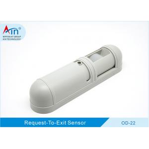
OD22; Specifically Designed Request To Exit Sensor , Rex Motion Detector For Indoor
Brand Name:ALEPH
Certification:CE ISO
Model Number:OD-22
Minimum Order Quantity:1pcs
Delivery Time:25-30 days
Payment Terms:TT IN ADVANCE
Contact Now
Add to Cart
Active Member
Location:
Shenzhen Guangdong China
Address:
No. 301A, 3F, C6 Bldg, Hengfeng,No 739 Zhoushi Rd,Hezhou, Hangcheng, Bao'an, Shenzhen City, 518000 China
Supplier`s last login times:
within 11 hours
Product Details
Company Profile
Product Details
REQUEST-TO-EXIT Passive Infrared Sensor
DESCRIPTION
This motion sensor is specifically designed for Request-to-Exit
(REX) applications. It also detects motion in its coverage area and
signals an access control system or door control device
The OD-22 passive infrared Sensor is specifically designed for
to-exit applications , Standard OD-22 include qualified motion
analysis. The OD-22 may be mounted toframe header,wall or ceiling.
Intended for indoor use only.
FEATURES
• Adjustable second time delay
• Micro-based signal processing
• High sensitivity
• Available in white or brown enclosure
1. SPECIFICATIONS
| Supply Voltage | 12-24VDC or VAC . | ||||
| Supply Current | 18-30mA@12-24VDC,45-80mA@12-24VAC | ||||
| Relay Output | 2C Contact(N.C/N.O) , 24VDC 1A Max. | ||||
| Detection Type | Passive infrared | ||||
| Relay Hold Time | 0.5-64 seconds | ||||
| LED Indication | Red | ||||
| Range | Coverage 12x5 ft at 7ft high,30x12 ft at 15 ft high(Adjustment ) | ||||
| Operating Temperature | - 14°F to 131°F(- 10° C to 55°C) | ||||
| Weight | 0. 4lb( 0. 18kg) | ||||
| Humidity | 0-95% non-condensing | ||||
| Dimensions | 6.53"Wx1. 57"Hx1. 53"D( 166x40x39mm) |
2. DIMENSIONS
3. DESCRIPTION AND OPERATION
4. DETECTION PATTERN
5. INSTALLATION
Mounting Procedure
1. Select a mounting location over the center of the door or doors
to be covered. The target must walk
directly toward the detector.Mount the detector on the
ceiling,wall,or door frame.
2. Remove the front cover from the detector.
3. Route the wiring as necessary through the wiring entrance(refer
to the item 3 description and oper- ation).For surface wiring,use
the break out wiring entrance on the front cover(at the same end as
the wire entrance).
4. Loosely mount the back cover to the mounting sur- face using the
supplied mounting screws.
5. Aim the detector for the desired coverage.
6. Mount the front cover on the detector.
Long Range/Short Range Adjustment
The OD-22 can be set to detect individuals at either a long
rang(several steps from the door) or at short range (immediately in
front of the door).If the build- ing includes a lengthy approach to
the exit doorway and no other foot traffic in the area, choose the
long range setting.
Setup and Testing
1. Apply power to the unit.
2. Wait at least 3 min for the detector to settle.
3. Test the unit by walking directly throgh the coverage area,to-
ward the door.
4. Aim the detector up or down if necessary to obtain the proper
coverage.
5. Check that the relay latch time is sufficient Adjust if
necessary.
6. After confirming proper operation,replace the cover and walk
test one more time to ensure the coverage has not changed.
6. WIRING
Latch Time
DIP Switch 1,2,and 3 set the relay time.Latch time is adjustable
from 0.5 sec to 64 sec.It indicates the amount of time the relay
can remain active after the detector first sees motion.
| Table1: Latch Time DIP Switch Settings | ||||||
| Time(sec) | Switch 1 | Switch 2 | Switch 3 | |||
| 0.5(Default) | OFF | OFF | OFF | |||
| 1 | ON | OFF | OFF | |||
| 2 | OFF | ON | OFF | |||
| 4 | ON | ON | OFF | |||
| 8 | OFF | OFF | ON | |||
| 16 | ON | OFF | ON | |||
| 32 | OFF | ON | ON | |||
| 64 | ON | ON | ON | |||
| Table 2: LED Enable/Disable DIP Switch Settings | |||||
| Switch 4 | Function | ||||
| OFF | Disabled | ||||
| ON | Enabled (Default) | ||||
| Table 3:Relay Mode DIP Switch Settings | |||||
| Switch 5 | Function | ||||
| OFF | Fail Secure | ||||
| ON | Fail safe(Default) | ||||
| Table 4:Resettable/Non-resettable DIP Swithc Settings | |||||
| Switch 6 | Function | ||||
| OFF | Non-resettable | ||||
| ON | Resettable (Default) | ||||
7. TROUBLE SHOOTING AND MAINTENANCE
| TROUBLE | TROUBLE CAUSE | REMEDY | |||||||
| Unit does not power up | No or low imput power. | Apply proper input voltage. | |||||||
| Input power polarity reversed. | Correct wiring polarity. | ||||||||
| Alarm LED does not light | LED jumper is set to “LED OFF”. | Set LED jumper to “LED ENABLE” | |||||||
| Incorrect sensor mounting height | Increase / decrease mounting height | ||||||||
| LED indicates light,no signal output | Incorrect wiring at output terminals | Correct wiring fault. | |||||||
| Lightning damage | Replace sensor. | ||||||||
| Unit continues to operate after the input power has been disconnected. | The wire to the “V-” power input was discon- nected, the “V+” is still connected. | Disconnect wire from the “V+” power input. | |||||||
MAINTENANCE
INSPECTION: An inspection of this unit should be made periodically, consisting
of ,but not limited to all mounting, wiring
and the condition of the interior area and components.
CLEANING : Clean the plastic parts of this unit with a soft, clean, cloth
dampened with water.
TESTING : This unit should be tested rouinely for proper operation. At a
minimum, operation should be fully checked yearly.


OD22; Specifically Designed Request To Exit Sensor , Rex Motion Detector For Indoor
Inquiry Cart
0