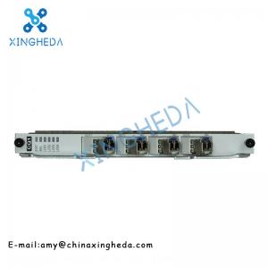
HUAWEI CQ1 SL91 4-Port Channelized STM-1 For Huawei Interface Board
Brand Name:HUAWEI
Model Number:CQ1
Minimum Order Quantity:1pc
Delivery Time:3-7 work days
Payment Terms:T/T, Western Union, MoneyGram
Place of Origin:CHINA
Contact Now
Add to Cart
Verified Supplier
Location:
Changsha Hunan China
Address:
2506 Xidi Building, No. 8 Fenglin Third Road, Yuelu District, Changsha City, Hunan Province
Supplier`s last login times:
within 1 hours
Product Details
Company Profile
Product Details
HUAWEI CQ1 SL91 4-port channelized STM-1 for Huawei interface board
Product Description:
The functional version of CQ1 boards is SL91.
Application:
CQ1 boards apply to OptiX RTN 910 NEs to transparently transmit STM-1 services over packet radio networks. CQ1 boards receive/transmit only channelized STM-1 services.
CQ1 boards are used in the following scenarios:
STM-1 services are transparently transmitted over packet radio networks.
Multiprotocol Label Switching (MPLS) tunnels traverse a TDM network.
Circuit emulation service (CES) E1 services are converged to channelized STM-1s.
Transparently Transmitting STM-1 Services over Packet Radio Networks
Figure 1 Application scenario of CQ1 boards (1)
Carrying MPLS Tunnels over a TDM Network
Figure 2 Application scenario of CQ1 boards (2)
Converging CES E1 Services to Channelized STM-1s
Figure 3 Application scenario of CQ1 boards (3)
NOTE:
The IF boards shown in Figure 1 to Figure 3 must be general-purpose IF boards or cross polarization interference cancellation (XPIC) IF boards working in native E1+Ethernet or native STM-1+Ethernet mode.
Functions and Features:
CQ1 boards receive and transmit four channels of channelized STM-1 optical/electrical signals.
Table 1 lists the functions and features supported by CQ1 boards.
Table 1 Functions and features that CQ1 boards support.
| Function and Feature | Description | |
| Basic functions | Receives and transmits four channels of channelized STM-1 optical/electrical signals. | |
| Supported packet service types | Circuit emulation service (CES) E1 ML-PPP E1 | |
| Port specifications | Optical ports | Use small form-factor pluggable (SFP) optical modules and support optical ports of the Ie-1, S-1.1, L-1.1, and L-1.2 types. Comply with ITU-T G.957. |
| Electrical ports | Use SFP electrical modules. Comply with ITU-T G.703. | |
| Fractional E1 | Transparently transmits 64 kbit/s CES services. | |
| CES | Maximum number of services | 80 |
| Encapsulation mode | CESoPSN (CESoPSN stands for circuit emulation services over packet switch networks) SAToP (SAToP stands for Structure-Agnostic Time Division Multiplexing over Packet) | |
| Idle timeslot compression | Supported only in CESoPSN mode | |
| Jitter buffering time (us) | 875 to 16,000 | |
| Packet loading time (us) | 125 to 5,000 | |
| CES ACR(ACR stands for adaptive clock recovery) | Supported, but the NE can only function as a master node | |
| Transparent transmission of SDH overheads | Supported | |
| ML-PPP | Type of links carrying ML-PPP links | E1s in channelized STM-1s |
| Maximum number of supported PPP links | 252 | |
| Maximum number of supported ML-PPP groups | 32 | |
| Maximum number of links in one ML-PPP group | 16 | |
| Clock | Clock source | Each line port provides one channel of SDH line clock signals. Each board supports two channels of E1 clock signals over its STM-1 ports. |
| Clock protection | Protection implemented by providing clock sources with different priorities Protection implemented by running Synchronization Status Message (SSM) protocol Protection implemented by running extended SSM protocol | |
| SDH line clock retiming | Supported | |
| Linear multiplex section protection (MSP) | 1:1 linear MSP | |
| DCN | Outband DCN | Each SDH line port can provide one data communications channel (DCC) that is composed of three DCC bytes, nine DCC bytes, or 12 DCC bytes. |
| Inband DCN | Transmits DCN information over ML-PPP links. | |
| Operation and maintenance | Loopback | Supports inloops at STM-1 ports. Supports outloops at STM-1 ports. Supports inloops over E1 channels. Supports outloops over E1 channels. |
| Warm and cold resetting | Supported | |
| Switching a laser on or off | Supported | |
| Manufacturer information querying | Supported | |
| Power consumption querying | Supported | |
| SFP module information detecting and querying | Supported | |
Working Principle and Signal Flow:
This section describes how the function units of a CQ1 board process channelized STM-1 optical signals.
Function Block Diagram
Figure 1 CQ1 board function block diagram
Signal Processing in the Receive Direction
Table 1 Signal processing in the receive direction of a CQ1 board
| Step | Function Unit | Processing Flow |
| 1 | Signal interface unit | Receives channelized STM-1 signals. Regenerates STM-1 optical signals. Checks for R_LOS alarms. Converts STM-1 optical signals into STM-1 electrical signals. |
| 2 | SDH processing unit | Restores clock signals. Synchronizes frames and checks for R_LOS and R_LOF alarms. Descrambles signals. Checks B1 and B2 bytes and generates alarms and performance events, if any. Checks the M1 byte and bits 6-8 of the K2 byte, and generates alarms and performance events, if any. Checks for changes in Synchronization Status Messages (SSMs) in the S1 byte and reports the SSM status to the system control and communication unit. Extracts orderwire bytes, auxiliary channel bytes (including F1 and serial bytes), DCC bytes, and K bytes, and transmits the bytes to the logic processing unit. Adjusts AU pointers and generates performance events, if any. Checks higher order path overheads and generates alarms and performance events, if any. Decapsulates E1 signals from the STM-1 signals. |
| 3 | Packet processing unit | Frames E1 signals. Performs CES emulation. Performs Multilink Point-to-Point Protocol (MP-PPP) processing. Encapsulates PWE3 services and converts them into Ethernet services. |
| 4 | Logic processing unit | Grooms services from service buses to the GE bus on the backplane. Sends service signals to the packet switching unit. |
Signal Processing in the Transmit Direction:
Table 2 Signal processing in the transmit direction of a CQ1 board
| Step | Function Unit | Processing Flow |
| 1 | Logic processing unit | Receives service signals from the packet switching unit. Grooms services from the GE bus on the backplane to service buses. |
| 2 | Packet processing unit | Decapsulates service signals. Restructures CES packets. Converts signals into E1 signals and sends the E1 signals to the SDH processing unit. |
| 3 | SDH processing unit | Multiplexes E1 signals into STM-1 signals. Sets higher order path overheads. Sets AU pointers. Sets multiplex section overhead bytes. Sets regenerator section overhead bytes. Scrambles signals. |
| 4 | Signal interface unit | Converts electrical signals into optical signals. |
Control Signal Processing:
The CQ1 board is directly controlled by a CPU on the system control and communication unit. The CPU issues configuration and query commands to other units of the board over the control bus. These units send command responses, alarms, and performance events to the CPU unit over the control bus.
The logic control unit decodes the address read/write signals from the CPU.
Power Supply Unit
The power supply unit receives two -48 V power supplies from the backplane. It then converts the -48 V power supplies into +3.3 V power and supplies the +3.3 V power to other units on the board.
Clock Unit
The clock unit performs the following operations:
Extracts line clock signals or E1 clock signals and transmits them to the system control and communication unit.
Receives system clock signals from the control bus on the backplane and supplies clock signals to other units on the board.
Front Panel:
A CQ1 board has indicators and STM-1 ports on its front panel.
Front Panel Diagram
Figure 1 Front panel of a CQ1 board providing optical ports
Figure 2 Front panel of a CQ1 board providing electrical ports
If you are interested, please let us know the specific model. We
will provide the best service and the best price!
Pr


HUAWEI CQ1 SL91 4-Port Channelized STM-1 For Huawei Interface Board
Inquiry Cart
0