
Add to Cart
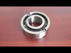
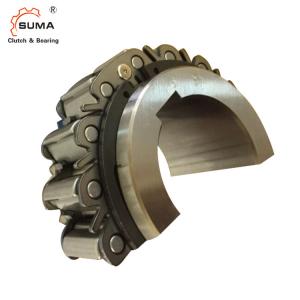
BR20 One way 35MM H6 H7 1.3KG Overrunning Cam Clutch Bearing
1. We recommend using shaft tolerances of h6 or h7 for Cam Clutch
installation.
2. Use a ISO R773 (DIN 6885.1) parallel key make sure that the key
does not move in the keyway. A loose key will damage the Cam
Clutch.
3. When installing the Cam Clutch over a shaft, please follow the
procedure outlined below. Never strike the clutch with a steel
hammer or apply unnecessary impact loads.
1) Verify Cam Clutch direction of rotation. The arrow on the inner
race shows the free running (cam disengaged) direction. Make sure
that the direction of cam engagement matches the intended
application.
2) Tap the inner race lightly with a soft hammer moving around the
race circumference so the Cam Clutch moves slowly and uniformly
onto the end of the shaft. Make sure that the outer race does not
become dislodged.
3) Place an end plate over the inner race and use the mounting
bolts to pull the Cam Clutch onto the shaft as shown in the diagram
at right.
4) Tighten the end plate securely.
Dimensions and Capacities
■ MODELS BR20 TO BR240
For Backstop and Overrunning Applications
| Model | Bore Size | A | B | C (h7) | D (h7) | E | F | Mounting Holes | Pulloff Holes | H min | I | J | K | L | M max | |||
Dia. (H7) | Keyway | Chamfer O | PCD | No.-Dia. | No.-Size | |||||||||||||
| G | Q-R | S-T | ||||||||||||||||
| BR 20 | 20 | 6x2.8 | 0.5 | 35 | 35 | 90 | 66 | 40.7 | 40.7 | 78 | 6- 6.6 | 2-M 6 | 53 | 0 | 0 | 5 | 5 | 4.0 |
| BR 25 | 25 | 8x3.3 | 0.5 | 35 | 35 | 95 | 70 | 44.7 | 44.7 | 82 | 6- 6.6 | 2-M 6 | 58 | 0 | 0 | 5 | 5 | 4.0 |
| BR 30 | 30 | 8x3.3 | 1.0 | 35 | 35 | 100 | 75 | 49.7 | 49.7 | 87 | 6- 6.6 | 2-M 6 | 64 | 0 | 0 | 5 | 5 | 4.0 |
| BR 35 | 35 | 10x3.3 | 1.0 | 35 | 35 | 110 | 80 | 54.7 | 54.7 | 96 | 8- 6.6 | 2-M 6 | 70 | 0 | 0 | 5 | 5 | 4.0 |
| BR 40 | 40 | 12x3.3 | 1.0 | 35 | 35 | 125 | 90 | 64.7 | 64.7 | 108 | 8- 9.0 | 2-M 8 | 81 | 0 | 0 | 5 | 5 | 4.0 |
| BR 45 | 45 | 14x3.8 | 1.0 | 35 | 35 | 130 | 95 | 69.7 | 69.7 | 112 | 8- 9.0 | 2-M 8 | 86 | 0 | 0 | 5 | 5 | 4.0 |
| BR 50 | 50 | 14x3.8 | 1.0 | 40 | 40 | 150 | 110 | 84.7 | 84.7 | 132 | 8- 9.0 | 2-M 8 | 103 | 0 | 0 | 7.5 | 7.5 | 6.5 |
| BR 60 | 60 | 18x4.4 | 1.5 | 60 | 50 | 175 | 125 | 80 | 80 | 155 | 8-11.0 | 2-M10 | 110 | 5 | 5 | 7 | 7 | 6.0 |
| BR 70 | 70 | 20x4.9 | 1.5 | 60 | 50 | 190 | 140 | 95 | 95 | 165 | 12-11.0 | 2-M10 | 125 | 5 | 5 | 7 | 7 | 6.0 |
| BR 80 | 80 | 22x5.4 | 1.5 | 70 | 60 | 210 | 160 | 115 | 115 | 185 | 12-11.0 | 2-M10 | 148 | 5 | 5 | 12 | 12 | 11.0 |
| BR 90 | 90 | 25 x5.4 | 1.5 | 80 | 70 | 230 | 180 | 135 | 135 | 206 | 12-13.5 | 2-M12 | 170 | 5 | 5 | 17 | 17 | 16.0 |
| BR100 | 100 | 28x6.4 | 1.5 | 90 | 80 | 270 | 210 | 143 | 143 | 240 | 12-17.5 | 2-M16 | 180 | 5 | 5 | 13.7 | 13.7 | 12.0 |
| BR130 | 130 | 32 x7.4 | 2.0 | 90 | 80 | 310 | 240 | 173 | 173 | 278 | 12-17.5 | 2-M16 | 210 | 5 | 5 | 13.7 | 13.7 | 12.0 |
| BR150 | 150 | 36x8.4 | 2.0 | 90 | 80 | 400 | 310 | 243 | 243 | 360 | 12-17.5 | 2-M16 | 280 | 5 | 5 | 13.7 | 13.7 | 12.0 |
| BR180 | 180 | 45x10.4 | 2.0 | 105 | 80 | 400 | 310 | 290 | 270 | 360 | 12-17.5 | 2-M16 | 280 | 5 | 20 | 11.5 | 15.9 | 14.0 |
| BR190 | 190 | 45x10.4 | 2.0 | 105 | 80 | 420 | 330 | 310 | 286 | 380 | 16-17.5 | 2-M16 | 300 | 5 | 20 | 12.5 | 8.9 | 7.5 |
| BR220 | 220 | 50x11.4 | 2.0 | 105 | 80 | 460 | 360 | 340 | 320 | 410 | 18-17.5 | 2-M16 | 330 | 5 | 20 | 12.5 | 10.9 | 9.0 |
| BR240 | 240 | 56x12.4 | 2.0 | 105 | 80 | 490 | 390 | 370 | 350 | 440 | 18-17.5 | 2-M16 | 360 | 5 | 20 | 12.5 | 10.9 | 9.0 |
| Model | Chamfer | U | Oil Plug Position/Dia. | Weight (kg) | Inertial Moment GD2 (kgm2) | |||
| N | P | V | W | X×PT-Y | ||||
| BR 20 | 1.5 | 1.5 | 30.0 | 17.5 | − | 4 × PT-1/16 | 1.3 | 2.25 × 10⁻⁴ |
| BR 25 | 1.5 | 1.5 | 30.0 | 17.5 | − | 4 × PT-1/16 | 1.4 | 3.28 × 10⁻⁴ |
| BR 30 | 1.5 | 1.5 | 30.0 | 17.5 | − | 4 × PT-1/16 | 1.5 | 4.44 × 10⁻⁴ |
| BR 35 | 1.5 | 1.5 | 22.5 | 17.5 | − | 4 × PT-1/8 | 1.9 | 5.65 × 10⁻⁴ |
| BR 40 | 1.5 | 1.5 | 22.5 | 17.5 | − | 4 × PT-1/8 | 2.4 | 1.01 × 10⁻³ |
| BR 45 | 1.5 | 1.5 | 22.5 | 17.5 | − | 4 × PT-1/8 | 2.6 | 1.22 × 10⁻³ |
| BR 50 | 2.5 | 2.0 | 22.5 | 20 | − | 4 × PT-1/8 | 4.1 | 2.64 × 10⁻³ |
| BR 60 | 3.5 | 2.0 | 22.5 | 25 | − | 4 × PT-1/8 | 7.3 | 3.73 × 10⁻³ |
| BR 70 | 3.5 | 2.0 | 15.0 | 25 | − | 4 × PT-1/8 | 8.1 | 6.65 × 10⁻³ |
| BR 80 | 3.5 | 2.0 | 15.0 | 14 | 32 | 4 × PT-1/8 | 12.0 | 1.77 × 10⁻² |
| BR 90 | 3.5 | 2.0 | 15.0 | 19 | 32 | 4 × PT-1/8 | 16.0 | 3.16 × 10⁻² |
| BR100 | 4.5 | 2.0 | 15.0 | 20 | 40 | 4 × PT-1/4 | 23.0 | 6.31 × 10⁻² |
| BR130 | 4.5 | 2.0 | 15.0 | 20 | 40 | 4 × PT-1/4 | 31.0 | 0.109 |
| BR150 | 4.5 | 3.0 | 15.0 | 20 | 40 | 4 × PT-1/4 | 58.0 | 0.365 |
| BR180 | 4.5 | 3.0 | 15.0 | 20 | 40 | 4 × PT-1/4 | 60.0 | 0.435 |
| BR190 | 4.5 | 3.0 | 11.25 | 20 | 40 | 4 × PT-1/4 | 65.0 | 0.563 |
| BR220 | 4.5 | 3.0 | 10.0 | 20 | 40 | 4 × PT-1/4 | 76.0 | 0.789 |
| BR240 | 4.5 | 3.0 | 10.0 | 20 | 40 | 4 × PT-1/4 | 84.0 | 1.05 |
Notes:
1. Package type Cam Clutches are all made to order. To order, please refer to the dimension diagram. Please inform us if the Cam Clutch is to be used in a vertical application, and if the operating environment temperature will be less than –5°C or more than +40°C.
2. There are cases when the free running rotation speed of the inner race will be limited when package type Cam Clutches are installed horizontally,
3. If your application calls for a clutch engagement speed or inner race free running speed not listed in this catalog,please contact TSUBAKI .
Capacities (Open Type)
ModelTorque Capacity (N·m)Inner Race Overrunning SpeedMax. Engagement(r/min)Min.(r/min)Max. (r/min)BR 203068803,600350BR 253848803,600350BR 306078803,600350BR 356867803,600300BR 409807203,600300BR 451,0786703,600280BR 501,7156103,600240BR 603,4794903,600200BR 704,7354803,600200BR 806,5174503,600190BR 908,5264203,000180BR10014,2104602,700180BR13020,3844202,400180BR15033,9083701,300160BR18033,9083703,500160BR19041,1603403,000140BR22051,0583303,000140BR24062,0343103,000130Dimensions (Package Type)
| Model | Bore Size(H7) | Keyway | A | B | C(h7) | D | PCDE | F-G | weight(kg) |
| BR 20P | 20 | 6X2.8 | 87 | 79 | 94 | 35 | 78 | 6-M 6×12 | 3.4 |
| BR 25P | 25 | 8X3.3 | 89 | 81 | 98 | 40 | 82 | 6-M 6×12 | 3.8 |
| BR 30P | 30 | 8X3.3 | 94 | 85 | 103 | 45 | 87 | 6-M 6×12 | 4.3 |
| BR 35P | 35 | 10X3.3 | 94 | 85 | 112 | 50 | 96 | 8-M 6×12 | 5.1 |
| BR 40P | 40 | 12X3.3 | 100 | 91 | 130 | 55 | 108 | 8-M 8×16 | 7.5 |
| BR 45P | 45 | 14X3.8 | 100 | 91 | 135 | 60 | 112 | 8-M 8×16 | 7.9 |
| BR 50P | 50 | 14X3.8 | 107 | 98 | 152 | 70 | 132 | 8-M 8×16 | 10.9 |
| BR 60P | 60 | 18X4.4 | 122 | 112 | 180 | 80 | 155 | 8-M10×20 | 17.5 |
| BR 70P | 70 | 20X4.9 | 128 | 118 | 190 | 90 | 165 | 12-M10×20 | 19.5 |
| BR 80P | 80 | 22X5.4 | 148 | 134 | 210 | 105 | 185 | 12-M10×20 | 27 |
| BR 90P | 90 | 25X5.4 | 152 | 138 | 235 | 120 | 206 | 12-M12×24 | 35 |
| BR100P | 100 | 28X6.4 | 186 | 172 | 275 | 140 | 240 | 12-M16×32 | 60 |
| BR130P | 130 | 32X7.4 | 208 | 188 | 314 | 160 | 278 | 12-M16×32 | 80 |
| BR150P | 150 | 36X8.4 | 226 | 204 | 400 | 200 | 360 | 12-M16×32 | 151 |
| BR180P | 180 | 45X10.4 | 240 | 218 | 400 | 220 | 360 | 12-M16×32 | 169 |
| BR190P | 190 | 45X10.4 | 250 | 242 | 420 | 240 | 380 | 16-M16×32 | 193 |
| BR220P | 220 | 50X11.4 | 250 | 242 | 460 | 260 | 410 | 18-M16×32 | 220 |
| BR240P | 240 | 56X12.4 | 260 | 252 | 490 | 280 | 440 | 18-M16×32 | 267 |
Note: Above drawing is an example. Request a certified drawing when ordering, as specifications vary with each model.
Capacities (Package Type)
ModelTorque Capacity (N·m)Inner Race Overrunning SpeedMax. Engagement(r/min)Min.(r/min)Max. (r/min)BR 20P3068803,600350BR 25P3848803,600350BR 30P6078803,600350BR 35P6867803,600300BR 40P9807203,600300BR 45P1,0786703,600280BR 50P1,7156103,600240BR 60P3,4794903,600200BR 70P4,7354803,600200BR 80P6,5174503,600190BR 90P8,5264203,000180BR100P14,2104602,500180BR130P20,3844202,200180BR150P33,9083701,300160BR180P33,9083701,800160BR190P41,1603401,800140BR220P51,0583301,800140BR240P62,0343101,800130
■ USING THE BR SERIES OPEN TYPE CAM CLUTCH
While the Cam Clutch can be disassembled by the user, reassembly may prove difficult. We recommend that you
install the Cam Clutch as delivered.
Mounting and Coupling
Installation and Usage
4. If you are installing the outer race first, check the precision
of the fit. The tolerances for outer race mounting are shown in the
tables at right. Verify that the correct tolerances can be
obtained. Out of spec installation could damage the Cam Clutch.
5. To lubricate the Cam Clutch, apply lubricant at the outer
circumference of the inner race (see installation diagram). Avoid
over lubrication, as it will cause the Cam Clutch to generate
excessive heat.
6. When using the Cam Clutch at a reduction gearbox, make sure that
oil from the gearbox cannot enter the Cam Clutch. Service life can
be significantly shortened if the Cam Clutch comes in contact with
gear oils that contain viscosity enhancing additives. Refer to page
80 for lubrication guidelines.
7. When installing a cover or seal support over the outer race, use
bolts with a tensile rating of 10.9 or greater. Use a sealing agent
or packing material between the mating services to prevent leakage.
■ USING THE BR SERIES PACKAGE TYPE CAM CLUTCH
Similar to previous types, the package type Cam Clutch is designed into a ball bearing cassette that makes
installation with a torque arm and/or coupling fast and easy. The package type Cam Clutch is grease lubricated.
Installation and Usage
1. We recommend using shaft tolerances of h6 or h7 for Cam Clutch
installation.
2. Use a ISO R773 (DIN 6885.1) parallel key. Make sure that the key
does not move in the keyway. A loose key will damage the Cam
Clutch.
3. When installing the Cam Clutch over a shaft, please follow the
procedure outlined below. Never hit the clutch with a steel hammer
or apply unnecessary impact loads.
1) Verify the Cam Clutch direction of rotation. The arrow on the
inner race shows the free running (cam disengaged) direction. Make
sure that the direction of cam engagement matches the intended
application.
2) Tap the inner race lightly with a soft hammer moving around the
race circumference so the Cam Clutch moves slowly and uniformly
onto the end of the shaft. Make sure that the outer race does not
become dislodged.
3) Place an end plate over the inner race and use the mounting
bolts to pull the Cam Clutch onto the shaft as shown in the diagram
at right.
4) Tighten the end plate securely to make sure that the Cam Clutch
cannot move on the shaft.
4. If you using a torque arm, make sure that the bolts used to
mount the torque arm have a tensile strength of 10.9 or greater,
and tighten them securely.
5. Set a 2mm clearance between the torque arm and the torque arm
stopper. If the torque arm is rigidly mounted, it will be applying
a load to the Cam Clutch which can eventually damage it.
6. Install an appropriate coupling if there is a chance that the
shaft will elongate from thermal expansion as encountered in some
exhaust fan auxiliary drive system applications.
7. If thrust loads are encountered, install a thrust bearing which
will prevent those thrust loads from being transferred to the Cam
Clutch.
8. The Cam Clutch is pre-packed with grease before shipment and is
ready for installation and operation. Refer to page 80 for
lubrication guidelines.
Pictures