
Add to Cart
DC9V~35V Smoke Detector For Detecting Smoke And Fire Inside Outdoor Telecom Cabinet
Model: EA4016001
1. Application
The smoke detector can provide protection for communication and electric BTs, and exactly detect smoke. When the concentration of smoke exceeds the preset threshold, the detector alarms and send alarm signal to the control panel. With high volume buzzer, the detector gives high volume sound. The alarm signal doesn’t lock-up, when the density of smog is below the preset threshold, the detector resumes monitoring state. With perfect thunder-proof circuit, the detector can operate normally at bad environment.
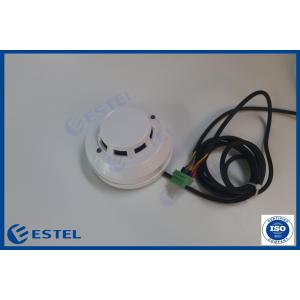
2. Product Picture
1.LED Indicator light;
2.Dust cover;
3.Maze;
4.Mounting base
3. Product Features
The product is a non coding smoke detector, with a pair of switch output contacts, which can choose the normally open and normally closed output according to the actual needs. In normal operation, the indicator light flashes every 8 seconds; in alarm, the indicator light is always on, and the alarm output contact acts at the same time.
4. Technical Parameters
| Working voltage | DC9V~35V |
| Standby current | 16mA (Relay normally closed) 3mA(Relay normally open) |
| Alarm current | 8mA(Relay normally closed) 19mA(Relay normally open) |
| Alarm indication | Red LED always on |
| Sensor | Infrared photoelectric sensor |
| Working temperature | -10°C ~ +50°C |
| Environment temperature | Max.95%RH (no condensation) |
| Anti RF interference | 10MHz—1GHz 20V/m |
| Alarm output | Normally open/normally closed optional, contact capacity DC28V 100mA |
| Reset mode | Automatic reset / power off reset optional |
| Coverage area | When the space height is 6m-12m, the protection area of a detector is 80 square meter for general protection site; when the space height is below 6m, the protection area is 60 square meter. The specific parameters shall be subject to the code for design of automatic fire alarm system GB50116-98. |
| Executive standard | GB4716—2005,EN54—7 |
| Sensitivity | 0.5db/m (±0.1db/m) |
| External dimension | 104mm(Diameter)﹡51mm(Height) |
5. Product installation
5.1 Select the appropriate installation location, generally installed on the ceiling in the center of the detector coverage area.
5.2 Connect the power line and signal line to the mounting base (mounting base “1” and “2” are no polarity input for power supply; “3” and “4” are alarm output contact).
5.3 Description of blue two digit dial switch
"2" corresponds to KT control switch
"1" corresponds to RST control switch
5.3.1 KT alarm output setting
When the KT switch "2" is pulled to the letter "on", the relay is normally closed.
When the KT switch "2" is pulled to the letter "off", the relay is normally open.
5.3.2 RST alarm mode
When RST switch "1" is pulled to the letter "on", it is automatic reset.
When RST switch "1" is pulled to the letter "off", it is power off reset.
5.4 Screw the mounting base to the ceiling.
5.5 Align the locating convex point at the base end of the detector with the locating groove of the mounting base, and rotate clockwise to install the detector.
6. Notes
6.1 Pay attention to dust prevention. The dust cover can only be removed after the project is officially put into use.
6.2 There shall be no barrier within 0.5m around the detector.
6.3 The horizontal distance between the detector and the air supply hole of the air conditioner shall not be less than 1.5m.
6.4 The horizontal distance between detector and wall, beam edge shall not be less than 0.5m.
6.5 The detector shall be installed in the middle of the inner walkway ceiling with a width of less than 3m. The installation spacing of the detector shall not exceed 15m, and the distance between the detector and the end wall shall not be greater than half of the installation spacing of the control detector.
6.6 The detector should be installed horizontally. In case of inclined installation, the inclination angle should not be greater than 45 degree.
6.7 The detector base shall be installed firmly and its wire connection must be reliable.
6.8 It is recommended to conduct a simulated fire test once half a year to test whether the detector works normally.
7. Installation Inside Outdoor Telecom Cabinet


