30W Ultrasonic Element Impedance Analyzer For Transducer Converter Ceramic Rings
Brand Name:KnMTech
Model Number:KM-PV520A
Minimum Order Quantity:Negotiation
Delivery Time:3-15 work days
Payment Terms:L/C, T/T, Western Union
Place of Origin:China
Contact Now
Add to Cart
Active Member
Address:
No. 518, Weijing Road, Qiandeng Town, Kunshan , Jiangsu Province,China
Supplier`s last login times:
within 1 hours
Product Details
Company Profile
Product Details
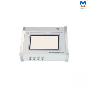
Ultrasonic element analyzer is used for the detection of piezoelectric ultrasonic devices and equipment integrated solutions. For a piezoelectric device, if there is no other resonance at a frequency far from a certain resonant frequency, the piezoelectric device can be approximated as a lumped system near the resonant frequency, and its symbols and equivalent circuits are shown in the lower-left figure:
Features:
1. The size is only 24cm*14cm*(10cm after the first 5cm), and the weight is only 1.95kg.
The most portable ultrasonic impedance analyzer in the world.
2. Oversized touch screen, no physical button is needed to display all parameters and graphics at one time, which is more intuitive.
3. Superfast test speed, a test of 1000 points only takes 5 seconds.
4. It can also be connected to a computer, and the software is fully compatible with PV70A/80A.
5. The maximum test frequency is up to 5MHz.
6. The only physical button on the instrument is also a "start" function, located at the back of the instrument panel
Graphics Introduction:
The system default display is "admittance circle graph" + "logarithmic graph";
admittance circle graph: The trajectory of admittance as a function of frequency displayed in polar coordinates.
logarithmic graph: The red line is the logarithmic curve of the impedance amplitude and the blue line is the impedance phase curve.
Parameters Introduction:
1. Resonant frequency Fs: The resonant frequency of the series branch in the equivalent circuit of the piezoelectric vibrator, at which the impedance of the piezoelectric vibrator is minimum.
2. Maximum conductance Gmax: The real part of the admittance value of the piezoelectric vibrator at resonance is the admittance real part at Fs.
3.Half power points F1 and F2: The admittance real part is equal to the frequency at Gmax / 2, and there are two such frequencies, F2 if greater than Fs and F1 if less than Fs
4. The inverse resonance frequency Fp: The resonant frequency of a parallel branch of a piezoelectric vibrator at which the piezoelectric vibrator has the greatest impedance
5. Free capacitance CT: Capacitance of piezoelectric devices at 1kHz frequency. This value is consistent with the measured value of the digital electricity bridge.
Detailed Photos:


30W Ultrasonic Element Impedance Analyzer For Transducer Converter Ceramic Rings
Inquiry Cart
0