PWM DC Motor LED Dimmer Speed Driver Controller Module With 5A Switching Function
Brand Name:YSONIX
Certification:Rohs
Model Number:YS-0088
Minimum Order Quantity:1
Delivery Time:1 working days
Payment Terms:L/C, D/A, D/P, T/T, Western Union, MoneyGram,Paypal
Contact Now
Add to Cart
Active Member
Location:
Shenzhen China
Address:
Rm3008 -Rm3009,Block A,JiaHe HuaQiang Building,Futian Disctrict,ShenZhen,China
Supplier`s last login times:
within 2 hours
Shipping
lt's easy to get a shipping quote! Just click the button below and complete the short form.
Get Shipping Quote
Product Details
Company Profile
Product Details
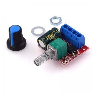
PWM DC Motor LED Dimmer Speed Driver Controller Module With 5A Switching Function
Product parameters:
| Working voltage | DC4.5V-28V |
| Output current | 0-5A |
| Output power | 90W (maximum) |
| Static Current | 7U A (Standby State) |
| PWM duty cycle | 1%-100% |
| PWM frequency | 20 kHz |
| Size | L30mm*W26mm*H14mm |
| Weight | 0.013KG |
Matters needing attention:
· DC motor governor input is DC, can not be directly connected to
AC (such as: 220V AC household), otherwise it will burn out!!!
· The positive and negative terminals of DC power supply should not
be connected back, otherwise the governor may be damaged.
· The motor can be positive or negative. When the direction of
operation is inconsistent with the expectation, the direction can
be changed by adjusting the line sequence.
· Adjusting potentiometer knob can change the duty cycle of
governor output and motor speed.
The working principle of the product module: the output voltage is changed by changing the duty cycle of the PWM, so as to change the speed of the motor. The so-called PWM is a pulse width modulator, which provides the motor with a pulse width adjustable with a certain frequency. The bigger the pulse width is, the bigger the duty cycle is. The bigger the average voltage provided to the motor, the higher the speed of the motor. On the contrary, the smaller the pulse width, the smaller the duty cycle. The smaller the average voltage provided to the motor, the lower the motor speed.
The basic principle of pulse width modulation (PWM): The control
mode is to control the on-off of the switching devices in the
inverting circuit, so that a series of pulses with equal amplitude
can be obtained at the output end, and these pulses can be used to
replace the sinusoidal wave or the required waveform. That is to
say, multiple pulses are generated in the half cycle of the output
waveform, so that the equivalent voltage of each pulse is
sinusoidal waveform, and the output is smooth and the low-order
harmonics are less. By adjusting the width of each pulse according
to certain rules, the output voltage and frequency of the inverter
circuit can be changed.
When the mobile phone is mounted on the WiFi module, the commands are sent in the following order:
(default baud rate 115200)
1. AT+CWMODE=2, that is, select AP mode;
2, AT + RST, reset;
3, AT + CIPMUX = 1, open multiple connections;
4, AT + CIPSERVER = 1, 8080, configure the TCP server, set the port number;
5, AT + CIOBAUD = 9600 set the baud rate to 9600. (Because the relay control chip works at the baud rate of 9600)
6. AT+CIFSR, check the IP address in AP mode, for example: APIP, "192.168.4.1";
7. The mobile phone connection name is the WIFI signal starting with AI-THINKER or ESP8266;
8. Enter the address and port in the "TCP Connection" APP, such as 192.168.4.1 and 8080;
9. Click on the corresponding gray square to control the relay.
FAQ:
Q: How long is your delivery time?
A: Normally 3-5 working days after payment; Special requirement orders, delivery time is negotiable.
Q: How long is your delivery time?
A: Normally 3-5 working days after payment; Special requirement orders, delivery time is negotiable.
Q: How to make sure the quality?
A:All product will be inspected by our strict QC department,warehouse,FAE,Sales before shipping.
Q:What is the warranty?
A:1-3 months to replace new items for free.
1-2 years repairing free according to different products.
Q:Do you accept OEM design?
A:Yes, we do. We can design according to your requirement, MOQ usually 1-10.
Q:Do you accept pay 30% in advance?
A:Yes, we do. We can start to prepare your goods when receive 30% payment, and send them after get the rest 70% payment.
Q:What payment terms you accept?
A:We accept Paypal, T/T, Alibaba Trade Assuarce, Western Union, Wechat, Alipay, in Cash (RMB or USD).
Pls contact us to check stock quantity,price ,lead time, E-mail: info@ysonix.com

PWM DC Motor LED Dimmer Speed Driver Controller Module With 5A Switching Function
Inquiry Cart
0