
Add to Cart
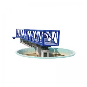
sedimentation tank of sewage treatment plant central drive mud scraper full bridge and half bridge sludge scraper
The central drive mud scraper is applicable to the sludge scraping
and discharging of the radial flow (circular) sedimentation tank
with a diameter generally not greater than 18m in the water plant
or sewage treatment plant in the water supply and drainage project.
The sludge is scraped to the central sludge collecting tank by the
scraper through the deceleration drive and the transmission of the
suspension component, and discharged out of the tank by the
hydrostatic pressure or pump.
Working Principle
The raw water of the central drive mud scraper flows to the
overflow tank around the pool after being distributed through the
central water distribution drum. With the decrease of the flow
rate, the suspended solids in the water body are separated and
settled at the bottom of the pool. The supernatant is discharged
from the overflow tank through the overflow weir plate.
Equipment Characteristics
1. The transmission part adopts electrical and mechanical double
overload protection, which makes the operation more safe and
reliable.
2. The underwater part is made of stainless steel, which has a long
corrosion resistance service life.
3. The effect of sludge scraping is good, and the moisture content
of discharged sludge is low.
Product Parameters
Parameter / model Pool widthΦ(m) | ZBGX-16 | ZBGX-20 | ZBGX-25 | ZBGX-30 | ZBGX-35 | ZBGX-40 | ZBGX-45 | ZBGX-50 | ZBGX-55 | |
| 16 | 20 | 25 | 30 | 35 | 40 | 45 | 50 | 55 | ||
| Deep pool depth H(m) | 3.5~4.5(According to the user's requirements) | |||||||||
| Pool side water depth H2(m) | 3.0~4.0(According to the user's requirements) | |||||||||
| Around the line speed V(m/min) | 1.8~2.2 | |||||||||
| Walking wheel dimensions (mm) | 400x120 | 420x150 | ||||||||
| Power of motor N(KW) | 0.37 | 0.55 | 0.75 | |||||||
| Installation size (mm) | Φ1 | 1100 | 1100 | 1200 | 1200 | 1500 | 1500 | 1800 | 1800 | 1800 |
| 2 | 2500 | 2500 | 2500 | 3500 | 4000 | 4500 | 5000 | 5500 | 6000 | |
| Φ3 | 2600 | 3000 | 3800 | 4500 | 4500 | 4500 | 5000 | 6000 | 6000 | |
| Φ4 | 2100 | 2300 | 3500 | 4000 | 4000 | 4000 | 4500 | 4500 | 4500 | |
| H2 | 500 | 500 | 009 | 760 | 760 | 760 | 760 | 760 | 760 | |
| B | According to the user's requirements | |||||||||
| H3 | According to the user's requirements | |||||||||
| L | According to the user's requirements | |||||||||
| Around the wheel pressure P1(KN) | 9.0 | 11.5 | 15 | 19 | 22 | 25 | 28 | 30 | 32 | |
| Vertical load of the central platform P2(KN) | 17 | 23 | 30 | 37 | 82 | 100 | 112 | 122 | 175 | |
| Center load of center load P3(KN) | 9.5 | 13 | 17 | 22 | 28 | 28 | 30 | 32 | 40 | |