
Add to Cart
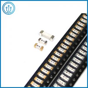
Non-Resettable Quick Blow Surface Mount Ceramic Fuse 1032 1A 2A 3.15A 350V 400V DC
Description Of The Non-Resettable Quick Blow Surface Mount Ceramic Fuse 1032
Non-resettable surface mount fuses are single-use circuit protection devices that break a circuit when a fault is detected. This type of fuse is designed to be mounted directly onto a printed circuit board (PCB).
Non-resettable surface mount fuses offer circuit protection by
breaking the circuit when detecting a fault. They are designed to
be mounted directly onto a printed circuit board (PCB) and are
available with a range of voltages, current ranges and resistance
levels. They work by melting the metal strip inside the fuse during
and overcurrent or short circuit event, which means they must be
replaced once the fuse has blown.
We supply a variety of non-resettable surface mount fuses suitable
for a range of applications, from manufacturers including one time
fuse and resettable fuse.
Features Of The Non-Resettable Quick Blow Surface Mount Ceramic Fuse 1032
► Fast-acting high current fuse
► Compact design utilizes less board space
► 1 A to 3.15A current ratings
► Ceramic tube, silver plated brass end cap construction
► DC 350V 400V
Application Of The Non-Resettable Quick Blow Surface Mount Ceramic Fuse 1032
► LED Driver
► Industrial application
► Telecom Devices
► Server and desktop power supplies
► Gaming console systems
► Voltage Regulator Module (VRM)
► Storage system power
► Base station power supplies
► Basic power supplies
► LED and general lighting
► Test equipment
Specification Of The Non-Resettable Quick Blow Surface Mount Ceramic Fuse 1032
| Attribute | Value |
| Current Rating | 1-3.15A |
| Fuse Size | 3 x 10 mm |
| Fuse Speed | F |
| Voltage Rating | 350V 400V DC |
| Body Material | Ceramic |
| Series | 1032F |
Ordering Info Of The Non-Resettable Quick Blow Surface Mount Ceramic Fuse 1032
Catalog No. | Ampere Rating | Voltage Rating | Breaking Capacity | Nominal Cold Resistance (Ohms) | I2TMelting Integral(A2.S) | Agency Approvals | |
| UL | cUL | ||||||
| R1032F.1100 | 1A | 350V/400V DC | 100A@350V/400V 50A@400V350V | 0.177 | 3.912 | ● | ● |
| R1032F.1125 | 1.25A | 0.122 | 7.040 | ● | ● | ||
| R1032F.1150 | 1.5A | 0.072 | 11.22 | ● | ● | ||
| R1032F.1160 | 1.6A | 0.071 | 12.53 | ● | ● | ||
| R1032F.1200 | 2A | 0.055 | 14.20 | ● | ● | ||
| R1032F.1250 | 2.5A | 0.041 | 28.02 | ● | ● | ||
| R1032F.1300 | 3A | 0.032 | 44.50 | ● | ● | ||
| R1032F.1315 | 3.15A | 0.031 | 45.20 | ● | ● | ||
Breaking Capacity: 50A@350V400Vdc,100A@350V400Vdc.
Operating Characteristics
% of Ampere Rating(In) | Blowing Time |
| 100% * In | 4 hours Min |
| 200% * In | 120 sec Max |
Choosing between a PTC and a Fuse
Overcurrent circuit protection can be accomplished with the use of
either a traditional fuse or the more recently developed resettable
PTC. Both devices function by reacting to the heat generated by the
excessive current flow in the circuit. The fuse melts open,
interrupting the current flow, and the PTC changes from a low
resistance to a high resistance to limit current flow.
Understanding the differences in performance between the two types
of devices will make the best circuit protection choice easier.
The most obvious difference is that the PTC is resettable. The
general procedure for resetting after an overload has occurred is
to remove power and allow the device to cool down. There are
several other operating characteristics that differentiate the two
types of products. The terminology used for PTCs is often similar
but not the same as for fuses. Two parameters that fall into this
category are leakage current and interrupting rating.
Leakage current: the PTC is said to have “tripped” when it has
transitioned from the low resistance state to the high resistance
state due to the overload. Protection is accomplished by limiting
the current flow to some leakage level. Leakage current can range
from around a hundred milliamps at rated voltage up to several
hundred milliamps at lower voltages. The fuse on the other hand
completely interrupts the current flow and this open circuit
results in “0” leakage current when subjected to the overload.
Interrupting rating: the PTC is rated for a maximum short circuit
current at rated voltage. This fault current level is the maximum
current that the device can withstand but the PTC will not actually
interrupt the current flow (see LEAKAGE CURRENT above). A typical
PTC short circuit rating is 40A. Fuses do in fact interrupt the
current flow in response to the overload and the range of
interrupting ratings goes from hundreds of amperes up to 10,000
amperes at rated voltage.
The circuit parameters may dictate the component choice based on
typical device rating differences.
Voltage rating: general use PTCs are not rated above 60V while
fuses are rated up to 600V. Current rating: the operating current
rating for PTCs can be up to 11A while the maximum level for fuses
can exceed 20A.
Temperature rating: the useful upper limit for a PTC is generally
85° while the maximum operating temperature for fuses is 125°C.
Both devices require derating for temperatures above 20°C and a
representative curve for that purpose is provided.
The PTC Rerating Curves located on data pages, should be consulted
for the proper rerating of the various PTC series at ambient
temperatures other than 20°C.
Additional operating characteristics can be reviewed by the circuit
designer in making the decision to choose a PTC or a fuse for
overcurrent protection.
Agency approvals: PTCs are recognized under the Component Program
of Underwriters Laboratories to UL Thermistor Standard 1434. The
devices have also been certified under the CSA Component Acceptance
Program. PTCs can, in addition, be approved to IECStandard 730-1
(Automatic Electric Controls) with certification by TUV, VDE, etc.
Approvals for fuses include recognition under the Component Program
of Underwriters Laboratories and certification from the CSA
Component Acceptance Program. In addition many fuses are available
with full “Listing” in accordance with the new Supplementary Fuse
Standard UL 248-14.
Resistance: Reviewing product specifications indicates that
similarly rated PTCs have about twice (sometimes more) the
resistance of fuses. Time-current characteristic: comparing the
time-current curves of PTCs to fuses shows that the speed of
response for a PTC is similar to the time delay of a Slo-Blow fuse.


