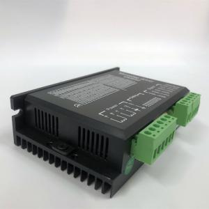
2 Phase Stepper Motor Driver Board Nema 34 Dm860d Stepper Driver
Brand Name:JSS
Certification:CE,ROHS,ISO
Model Number:DM860D
Minimum Order Quantity:1
Delivery Time:10 work days
Payment Terms:T/T,Paypal,credit card, Western Union
Contact Now
Add to Cart
Active Member
Location:
Changzhou Jiangsu China
Address:
No. 135 Dailuo Road, Luoyang Town, Wujin District, Changzhou City, Jiangsu province, China
Supplier`s last login times:
within 42 hours
Product Details
Company Profile
Product Details
2phase stepper motor driver nema 34 motor driver DM860D 24v stepper motor driver nema 34 stepper motor driver
Changzhou Jinsanshi mechatronics Co., Ltd., exporting stepper motors, servo motor,spindle motor,BLDC motor and their driver ,VFD. We spcialize in this field for many years, with the strength of high quality and competitive price in China.
We have our own techinical department and we developed various
models of stepper motor, we also have complete drawings for our
motors.
Product Description
Product Features:
1. Adoption of 32-bit DSP , pure sine wave subdivision technology.
2. Low-noise, low-vibration and low temperature rising
3. Voltage 24-80VDC
4. With 8 stalls output current setting,peak current 2.4-7.2A
5. With 16 stalls microstep subdivision setting.
6. Automatic Half current, self-test, over voltage, under voltage, over current protection
7. Internal optical isolation, highest frequency response 200KHZ
8. Suitable for current range nema 34 Hybrid stepper motor .
Applications
It can be applied in a variety of small scale automation equipment and instruments, such as labeling machine, cutting machine, packing machine, drawing machine, engraving machine, CNC machine and so on. It always performs well when it is used in equipment which requires for low-vibration, low-noise, high-precision and high-velocity.
Driver functions descriptions
| Driver function | Operating instructions |
Output current setting | Users can set the driver output current by SW1-SW3 three switches. The setting of the specific output current, please refer to the instructions of the driver panel figure. |
Microstep setting | Users can set the driver Microstep by the SW5-SW8 four switches. The setting of the specific Microstep subdivision, please refer to the instructions of the driver panel figure. |
Automatic half current function | Users can set the driver half flow function by SW4. "OFF" indicates the quiescent current is set to half of the dynamic current, that is to say, 0.5 seconds after the cessation of the pulse, current reduce to about half automatically. "ON" indicates the quiescent current and the dynamic current are the same. User can set SW4 to "OFF", in order to reduce motor and driver heating and improve reliability. |
Signal interfaces | PUL+ and PUL- are the positive and negative side of control pulse signal; DIR+ and DIR- are the positive and negative side of direction signal; ENA+ and ENA- are the positive and negative side of enable signal. |
Motor interfaces | A+ and A- are connected to a phase winding of motor; B+ and B- are connected to another phase winding of motor. If you need to backward, one of the phase windings can be reversed. |
Power interfaces | It uses DC power supply. Recommended operating voltage is 24VDC-80VDC, and power consumption should be greater than 350W. |
Indicator lights | There are two indicator lights. Power indicator is green. When the driver power on, the green light will always be lit. Fault indicator is red, when there is over-voltage or over-current fault, the red light will always be lit; after the driver fault is cleared, if re-power the red light will be off. |
Installation instructions | Driver dimensions:150×98×51mm, please refer to dimensions diagram. Please leave 10CM space for heat dissipation. During installation, it should be close to the metal cabinet for heat dissipation. |
Signal interface details:
The internal interface circuits of the driver are isolated by the opt coupler signals, R in the figure is an external current limiting resistor. The connection is differential. And it has a good anti-jamming performance.
Control signal and external interface:
| Signal amplitudes | External current limiting resistor R |
| 5V | Without R |
| 12V | 680Ω |
| 24V | 1.8KΩ |
Common indicator
| Phenomenon | Reason | Solution |
The red indicator is on. | 1. A short circuit of motor wires. | Inspect or change wires |
| 2. The external voltage is over or low than the driver’s working voltage. | Adjust the voltage to a reasonable rang | |
| 3. Unknown reason | Return the goods |
Outline and installation size (unit:mm)
Packing and shipment:
We have standard package for our products. We can also make it as per your special requirements.
Shipping can be arranged as per your requirements.
1. By sea
2. By Air
3. By Express, like DHL, Fedex, UPS etc.


2 Phase Stepper Motor Driver Board Nema 34 Dm860d Stepper Driver
Inquiry Cart
0