
Add to Cart
List of EO Modulators & Drivers
Phase Modulator
Intensity Modulator
Driver
The STK-AM series electro-optic intensity modulator utilizes the electro-optical effect of lithium niobate and push-pull Mach-Zehnder interference structure to achieve intensity modulation of optical signals. It features low insertion loss, high modulation bandwidth, high extinction ratio, low half-wave voltage and high damage optical power. This product is mainly used for electro-optical signal conversion in high-speed optical fiber communication systems, the generation of light sidebands, high extinction ratio light pulse generation in quantum communication, microwave fiber link and other fields.

Wavelengths optional
Low half-wave voltage
High bandwidth
Low insertion loss
High-speed optical fiber communication systems
Microwave fiber link
Quantum communication
| Parameters | Symbol | STK-AM-08 | STK-AM-10 | STK-AM-15-10G | STK-AM-15-20G |
| Wavelength | 830±40 | 1064±60 | 1550±100nm | 155±100nm | |
| Insertion loss | IL | <5 dB | <4 dB | <4 dB | <4.5 dB |
| Optical return loss | ORL | -40 dB | -45 dB | -45dB | -45dB |
| Bandwidth (-3dB) | S21 | 2.5GHz | 10GHz- | 10GHz | 20GHz |
| Rise time 10%~90% | tr | 150ps | 35ps | 35ps | 18ps |
| Half-wave voltage @50KHz, RF | Vπ | 5V | 4.5V | 4V | 5V |
| Half wave voltage @Bias | Vπ | 6V | 6V | 5V | 5V |
| Extinction ratio | ER | 28dB | 30dB | >25dB | >25dB |
| Input resistance | ZRF | 50 @RF, 1M @Bias | |||
| Electrical interface | SMA(f) | K(f) | |||
| Electrical return loss | S11 | <-10dB | |||
| Input fiber | PM Panda slow axis alignment | ||||
| Output fiber | Single mode fiber or PM fiber | ||||
| Fiber connector | FC/APC or customer specified | ||||
| Operating temperature | Top | -10~60C | |||
| Storage temperature | Tst | -40~80C | |||
| RF input power | Pi | <28dBm | |||
| Max. input optical power | Po | 30mW | 50mW | 100mW | 100mW |
1064nm Operation
Low insertion loss
3dB bandwidth 5GHz
Low half-wave voltage
High Extinction Ratio >50dB
Optical Pulse Generation
Optical fiber sensing system
Laser mode locking
The 1064nm high extinction ratio electro-optical intensity modulator integrates two Mach-Zehnder intensity modulators with a push-pull structure, which can achieve an extinction ratio of up to 50dB. It is used in the fields of high-speed optical pulse generation, fiber sensing, and laser mode locking.
| Parameters | Symbol | Min. | Typ. | Max. | Unit | ||
| Optical Parameters | |||||||
| Cystal | LiNbO3 X-Cut Y-Prop | ||||||
| Waveguide process | APE | ||||||
| Wavelength | 980 | 1064 | 1100 | nm | |||
| Insertion loss* | IL | 7 | 8 | dB | |||
| Optical return loss | ORL | -40 | dB | ||||
| Extinction ratio @DC | ER@DC | 50 | dB | ||||
| Polarization extinction ratio* | PER | 25 | 28 | dB | |||
| Fiber | Input | Panda PM 980 | |||||
| Output | Panda PM 980 | ||||||
| Fiber connector | FC/PC,FC/APC or user specified | ||||||
| Electrical Parameters | |||||||
| Bandwidth(-3dB) | S21 | 5 | GHz | ||||
| Half-wave voltage Vpi | RF1 & RF2 | Vπ@50KHz | 4.5 | 5 | V | ||
| Bias1 & Bias2 | Vπ@Bias | 4 | 5 | V | |||
| Electrical return loss | S11 | -12 | -10 | dB | |||
| Input impedance | RF1 & RF2 | ZRF | 50 | ||||
| Bias1 & Bias2 | ZBIAS | 1M | |||||
| Electrical connector | RF1 & RF2 | SMA(f) | |||||
| Bias1 & Bias2 | 4pin | ||||||
*with connector
| Parameters | Symbol | Unit | Min. | Typ. | Max. |
| Input optical power | Pin,Max | dBm | 10 | ||
| RF input power | dBm | 28 | |||
| Bias voltage | Vbias | V | -15 | 15 | |
| Operating temperature | Top | ºC | -10 | 60 | |
| Storage temperature | Tst | ºC | -40 | 85 | |
| Humidity | RH | % | 5 | 90 | |
| Dimension | mm | 111x12.5x9 |
STK-AM-10-BW-PP-FA/FP-HER
WL—Wavelength: 10-1064nm
BW—Bandwidth: 5G---5GHz
FA/FP—Connector: FA---FC/APC; FP---FC/PC
Key Features
C and L-Band Operation
Low insertion loss
3dB bandwidth 10GHz
Extinction ratio 35/40dB
Low half-wave voltage
Integrated Monitor Photodiode
Telecordia GR-468-CORE
Microwave fiber link
Quantum communication
Optical pulse generation
Optical fiber sensing system
Laser mode locking
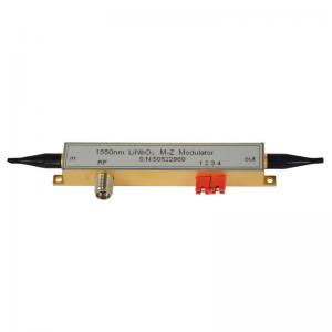
The 1550nm High Extinction Ratio LiNbO3 electro-optical intensity modulator based on the M-Z push-pull structure has a low half-wave voltage and stable physical and chemical characteristics, and the device has a high response rate, high extinction ratio(>40dB) and is therefore widely used in microwave fiber link, Quantum communication, optical Q-switched systems, laser mode-locking, and fiber sensing .
| Parameters | Symbol | Min. | Typ. | Max. | Unit | |
| Optical Parameters | ||||||
| Wavelength | 1525 | 1565 | nm | |||
| Insertion loss(with connector) | IL | 4 | 5 | dB | ||
| Optical return loss | ORL | -45 | dB | |||
| Extinction ratio @DC | ER@DC | 35 | 40 | dB | ||
| Fiber | Input | Panda PM Fujikura SM 15-P-8/125-UV/UV-400 | ||||
| Output | Panda PM Fujikura SM 15-P-8/125-UV/UV-400 | |||||
| Fiber interface | FC/PC,FC/APC or user specified | |||||
| Electrical Parameters | ||||||
| Bandwidth(-3dB) | S21 | 10 | 12 | GHz | ||
| Rise time (10%~90%) | Tr | 35 | ps | |||
| Half-wave voltage Vpi | RF | Vπ@50KHz | 5 | V | ||
| Bias | Vπ@Bias | 6 | V | |||
| Electrical return loss | S11 | -12 | -10 | dB | ||
| Photodiode Responsivity | RP | 10-3 | A/W | |||
| Input impedance | RF | ZRF | 50 | |||
| Bias | ZBIAS | 1M | ||||
| Electrical interface | SMA(f) | |||||
| Dimension | 111x12.5x9 | mm | ||||
| Parameters | Symbol | Unit | Min. | Typ. | Max. |
| Input optical power | Pin,Max | dBm | 20 | ||
| RF input power | dBm | 28 | |||
| Bias voltage | Vbias | V | -20 | 20 | |
| Operating temperature | Top | ºC | -10 | 60 | |
| Storage temperature | Tst | ºC | -40 | 85 | |
| Humidity | RH | % | 5 | 90 |
WL—Wavelength:15-1550nm
BW—Bandwidth:10G---10GHz 20G-20GHz
FA/FP—Connector:FA---FC/APC; FP---FC/PC
ER----Extinction Ratio: 35dB, 40dB
We can provide with the driver for the above electro-modulators and integrate the modulator, amplifier and relevant controllers together. The user can manually or automatically set the bias points. At the manual setting mode, the bias can be displayed and the EO modulator and amplifier individually operate. At the automatic setting mode, the user can set various bias points according to the demand and the bias point is locked and displayed. The modulation performance of the modulator is not influenced by external factors such as environment temperature and vibration.
| Symbol | Min | Typical | Max | Unit | ||
| Optical parameters | ||||||
| Wavelength | l | 1520 | 1550 | 1610 | nm | |
| Crystal | LiNbO3 | |||||
| Insertion loss | @Peak | IL | 4.5 | 5.5 | dB | |
| @Q | IL | 7 | 8 | dB | ||
| Optical return loss | ORL | -45 | dB | |||
| Extinction ratio @DC | ER@DC | 25 | 28 | dB | ||
| Fiber | Input | Panda PM Fujikura SM 15-P-8/125-UV/UV-400 | ||||
| Output | Corning SMF-28 | |||||
| Electrical parameters | ||||||
| Bandwidth (-3dB) | S21 | 10 | 12 | GHz | ||
| Working speed | 10K | 12.5G | bps | |||
| Input signal format | NRZ | |||||
| Input signal amplitude | Vi | 0.25 | 0.4 | 0.8 | Vpp | |
| Half-wave voltage @10Gbps | Vπ | 4.5 | 5.0 | V | ||
| Dynamic extinction ratio@10Gbps NRZ | DER | 12 | dB | |||
| Rise time (10%-90%) | Tr | 30 | 35 | ps | ||
| Additional vibration* | JitterRMS | 1.1 | 1.7 | 2.0 | ps | |
| Amplification gain | G | 0 | 25 | dB | ||
| Loss from waves | S11 | -12 | -10 | dB | ||
| Input impedance @RF input | ZRF | 50 | W | |||
| Manual setting mode | ||||||
| Bias voltage | Vbias | -10 | 10 | V | ||
| Adj. accuracy | 0.1 | V | ||||
| Automatic setting mode | ||||||
| Bias | Null, Q+/-, Peak | |||||
| Vibration period | F | 1 | KHz | |||
| Vibration amplitude | Vpp | 2%Vπ | ||||
| Harmonic extinction ratio | 40 | 50 | dB | |||
| Optical power stability | DP | 0.1 | dB | |||
| Duty | 45 | 55 | % | |||
| Other parameters | ||||||
| Input interface | SMA(f) | |||||
| Optical interface | Input | FC/APC PM | ||||
| Output | FC/APC SM | |||||
| Input power | VDC | AC 220 | V | |||
| Dimension | LxWxH | 270x300x90 | mm | |||
| Weight | <5 | kg | ||||
| Port | RS232 | |||||
| Display contents | Manual | Amplification gain, real-time bias voltage | ||||
| Automatic | Amplification gain, bias Vpi, real-time bias voltage, bias lock status | |||||
Ordering Information: STK-MU-W-XX-BW-FB-YY-M/A
W: wavelength such as 15-1550nm, 13-1310nm, 10-1064nm
XX: modulation method such as NRZ, DPSK, DQPSK, DPQPSK, AN, PM
BW: bandwidth such as 02-2.5G, 10-10G, 20-20G, 40-40G
FB: input/output fiber type such as PP (input & output are PM), PS (input is PM and output is SM)
YY: fiber connector such as FA-FC/APC, FP-FC/PC
M/A: control mode, M is manual and A is automatic.
The STK-KY-PM series electro-optic phase modulator utilizes the electro-optical effect of lithium niobate to achieve phase modulation of optical signals, and uses titanium diffusion or proton exchange process to fabricate optical waveguides, which can achieve dual-polarization or single-polarization phase modulation. It has low insertion loss, high modulation bandwidth, low half-wave voltage, high damage optical power, etc. This product is mainly used for optical chirp control in high-speed optical communication systems, phase delay in coherent communication systems, the generation of optical sidebands, phase modulation in quantum communication, reducing stimulated Brillouin scattering (SBS) in analog optical fiber communication systems and other fields.
Wavelengths optional
Low half-wave voltage
Low insertion loss
High damage optical power
Optical fiber sensing systems
Optical fiber communication
Laser coherent synthesis
Phase delay (movement)
Quantum communication
| Parameters | Symbol | STK-PM830-1 | STK-PM1064-1 | STK-PM1550-1 | STK-PM1550-2 |
| Wavelength | 830+/-40 | 1064+/-60 | 1550+/-50nm | ||
| Insertion loss | IL | <5 dB | <4 dB | <4 dB | 4 dB |
| Optical return loss | ORL | -40 dB | -45 dB | -45dB | -40 dB |
| Bandwidth (-3dB) | S21 | 2.5GHz | 10GHz- | 300MHz | 10GHz |
| Rise time 10%~90% | tr | 150ps | 35ps | 1ns | 35ps |
| Vpi@50KHz | Vπ | 5V | 4.5V | 4V | 4V |
| Input resistance | ZRF | 50 | 1M | 50 | |
| Electrical interface | SMA(f) | 3pin | SMA(f) | ||
| Electrical return loss | S11 | <-10dB | |||
| Input/output fiber | PM Panda slow axis alignment | ||||
| Fiber connector | FC/APC or customer specified | ||||
| Operating temperature | Top | -10~60C | |||
| Storage temperature | Tst | -40~80C | |||
| RF input power | Pi | <28dBm | |||
| Maximum input optical power | Po | 30mW | 100mW | 100mW | 100mW |
The STK-MU-SSB-15 series product is an optical CS-SSB modulation module developed by our company. The modulation module integrates Mach-Zehnder dual parallel modulators, bias point control circuits, 90 degree hybrid splitter, can achieve stable and reliable single sideband modulation, and can switch between left and right sideband control as needed. This product is mainly used in Brillouin fiber sensing systems, microwave photonics, gas detection and other fields.
Key Features
Wavelength C-band
Sideband suppression ratio:>30dB
Carrier suppression ratio: >26dB
Up and down sidebands
Convenient to use and reliable
Optical fiber sensing system
Microwave photonics
Gas detection
Optical fiber communication systems
| Parameters | Symbol | Min. | Typ. | Max. | Unit |
| Carrier Optical Source Parameters (Provided by the user) | |||||
| Laser type | DFB source or wavelength tunable source | ||||
| Wavelength | l | 1510 | 1560 | nm | |
| Line width | Dn | - | 1 | MHz | |
| Polarization extinction ratio | PER | 20 | - | dB | |
| Power | Pi | 10 | 100 | mW | |
| Modulator Specification Parameters | |||||
| Modulator type | X-cut double parallel M-Z modulator | ||||
| Modulator bandwidth S21@3dB | BW | 10 | 12 | - | GHz |
| Insertion loss | IL | 7 | 8 | dB | |
| Return loss | RL | -45 | -50 | - | dB |
| Bias Controller Parameters | |||||
| Automatic feedback bias controller | Jitter mode | ||||
| Jitter signal frequency | 400 | 1000 | 1400 | Hz | |
| Jitter signal amplitude | 10 | 50 | 1000 | mV | |
| Preset work point | Lowest point | ||||
| CS-SSB Optical Output Signal | |||||
| Single sideband modulation range* | F | 1 | 12 | GHz | |
| Input RF power | PRF | -5 | 5 | dBm | |
| Sideband suppression ratio @1550nm | 30 | 35 | - | dB | |
| Carrier suppression ratio @1550nm | 26 | 32 | dB | ||
| Interface | |||||
| Input fiber | Panda type polarization-maintaining fiber | ||||
| Output fiber | Panda type polarization-maintaining fiber | ||||
| Fiber optic interface | PM FC/APC Slow axis alignment | ||||
| Input RF signal interface | SMA(50Ω) | ||||
| Bias controller communication interface | J30J | ||||
| Other Parameters | |||||
| Operating temperature | To | +15 | - | +35 | ºC |
| Stored temperature | Ts | -40 | - | +75 | ºC |
| Power supply | V | - | 15 | - | V |
| Module size | LWH | 160*125*20 mm | |||
| Weight | - | 0.3 | - | Kg | |
Key Features
10G, 20G, 40GHz optional bandwidth
Gain> 25dB
Saturated output Max.25dBm (11Vpp)
Rise time Min.<8ps
Low jitter
DC12V power supply
Easy to use
High-speed optical fiber communication system
Quantum communication
Picosecond pulse amplification
Optical fiber sensing system
10G driver module
10G high output driver module
20G driver module
40G driver module
The STK-KY-MD-XX series electro-optic modulator driver is a broadband, high-output driver amplifier mainly used for lithium niobate electro-optical intensity and phase modulator. Its working bandwidth is up to 30K ~ 40GHz, and it can achieve a maximum of 42Gbps NRZ wideband signal amplification up to 8Vpp. It is mainly used in high-speed optical fiber communication systems, quantum communication, picosecond pulse amplification, and optical fiber sensing systems.
| Parameters | Symbol | Unit | STK-MD-10G | STK-MD-10G-HO | STK-MD-20G | STK-MD-40G | |
| Bandwidth(-3dB) | S21-High | GHz | >10 | >8 | >20 | >35 | |
| S21-Low | KHz | 30 | 100 | 30 | 30 | ||
| Data rate | bps | 100k~12.5G | 100k~10G | 100k~25G | 100k~42G | ||
| Gain | G | dB | >26 | >30 | >28 | >28 | |
| Gain ripple | DG | dB | <3 | <3 | <3 | <3 | |
| Output amplitude | Vout | Vpp | 8 | 11 | 8 | 8 | |
| Saturated output power | Ps | dBm | 23 | 25 | 23 | 23 | |
| Rise time (10% -90%) | Tr | ps | 35 | 40 | 18 | 8 | |
| Jitter | JitterRMS | ps | <2 | <2 | <1 | <1 | |
| Isolation | S12 | dB | <-40 | ||||
| Electrical return loss | S11 | dB | <-12 | <-10 | <-10 | <-10 | |
| RF connector | SMA(f) | K(f) | |||||
| Operating Voltage | VDC | V | DC 12V | ||||
| Working current | Io | mA | <500 | ||||
| Dimensions | LxWxH | mm | 50x33x15 | ||||
| Parameters | Symbol | Unit | Min. | Typ. | Max. |
| Input signal amplitude | Vin | Vpp | 1.5 | ||
| Operating Voltage | DC | V | 11.5 | 13 | |
| Operating temperature | Top | ºC | -20 | 60 | |
| Storage temperature | Tst | ºC | -40 | 85 |