
Add to Cart
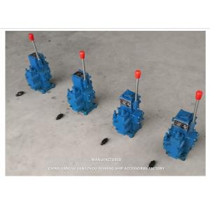
CSBF-H-G20 HYDRAULICS CONTROL VALVES MANUAL PROPORTIONAL FLOW CONTROL VALVES FOR SHIPS
PC CONTROL VALVES FOR SERIES HYDRAULIC CONTROL VALVE BLOCK MODEL-CSBF-20
| Model | Nominal diameter (mm) | Flow (L/min) | Pressure (MPA) | Safety valve pressure regulation (MPA) | Handle control force(N) | Mid-position spool valve function |
| CSBF-G20 | 20 | 120 | 25 | 5~25 | ≤40 | H-type |
The principle of pressure compensation mechanism for marine manual proportional flow composite valve CSBF-G20:
The oil in the motor pipeline flows from the inlet port (P port) of
the manual proportional valve to the load (A or B port) through the
throttle port of the main valve core. At the same time, the lower
part of the diverter valve core also receives a force that pushes
the valve core upwards. The magnitude of this force is P1A (A is
the cross-sectional area of the valve core). The pressure P1
decreases to P2 due to passing through the throttle port, and P2
acts on the upper part of the valve core to push the valve core
downwards, In addition, the action of the spring causes the valve
core to receive a downward pushing force, so the downward pushing
force is P2A+F (F is the spring force). If P2A+F>P1A is
established, the valve core is pushed downwards, causing the
throttle surface of the diverter valve to be closed, and all
incoming flow is directed to the load through the throttle port of
the main valve core. When the flow into the P port increases, P2A+F
is less than P1A. At this time, the valve core moves upwards and
the throttle surface opens, causing a large amount of flow to flow
out of the O port, reducing the flow through the throttle port
until F/A=P1 P2, and the valve core is in a stable state. If the
load pressure increases, and F/A>P1 P2, the valve core is pushed
downwards, reducing the opening of the flow surface, and P1 also
increases accordingly. Until F/A=P1 P2, the valve core is in a
stable state again. If the load pressure decreases, and F/A is less
than P1 P2, the valve core is pushed upwards, increasing the
opening of the throttle surface, and P1 decreases accordingly until
F/A=P1 P2, and the valve core is in a stable state again.
Therefore, regardless of how the inlet and outlet oil pressure
changes, the pressure difference P1-P2 remains constant, which
means that the flow rate when passing through the throttle is also
constant. Therefore, the flow rate is determined by its flow area
and is not related to the change in load pressure.
The direction switching and throttling principle of the main valve core of the CSBF-G20 manual proportional flow direction composite valve (taking the M-type as an example):
When the handle is in the middle position, each oil port (A, B
ports) is closed, and the oil discharged from the oil pump returns
from port P to port O, causing the oil motor to stop.
The handle is on the right side, and the main valve core moves
upwards. The oil flowing in from port P flows through the throttle
port to port A, and then flows out from port A to drive the oil
motor to rotate. The return oil of the oil motor returns from port
B to port O. At this time, the handle is used to adjust the opening
of the throttle port by adjusting the tilt angle of the main valve
core to different positions, in order to achieve the speed
regulation of the oil motor. On the contrary, when the handle is on
the left and the oil flows from P-B to A-O, the results are
completely similar, but the oil motor turns in the opposite
direction.
The overflow principle of the manual proportional flow composite valve CSBF-G20 for the anchor machine (safety valve part):
Like the principle of a general overflow valve, when the oil motor
is running and the load pressure is low, the cone valve is in a
closed state due to the action of spring force, and the oil motor
operates normally. When the load pressure increases and exceeds the
spring force pressed on the cone valve, the cone valve opens, and
high-pressure oil flows into port O from port P to protect the oil
motor.
Use and maintenance of CSBF-G20 manual proportional flow composite valve:
When we need to replace this CSBF manual proportional valve, we
encounter that the product identification nameplate has corroded.
We can accurately and quickly determine through the following
schematic diagram:
CHINA JIANGSU YANGZHOU FEIHANG SHIP ACCESSORIES FACTORY
COMPETITIVE ADVANTAGE
1. Factory direct sale, competitive price.
2. Customized Service: We can customize, to customers drawings for processing. We are flexible and capable Supplier.
3. Genuine Product with Excellent Quality: Our Product are strictly complied with China Compulsory Certification. 100% guarantee test before delivery.
4. After Sales Service and Technical Assistance: 24 hours technical support by email. Our professional team is always here willing to be your technical consultant.
5. Delivery Time: after receiving the payment within 24-72 hours to Timely arrange raw materials, processing, production, and timely delivery.

