ASME B16.47 Carbon Steel Flange Series A 26 Inch Welding Neck Blind Class 150
Brand Name:Kasugai
Model Number:ASME B16.47 Class 150 300 400 600 900
Minimum Order Quantity:Negotiable
Delivery Time:30 - 60 working days
Payment Terms:L / C , T / T
Place of Origin:China
Contact Now
Add to Cart
Verified Supplier
Location:
Shanghai Shanghai China
Address:
Rm.8415, Bldg. A8, No. 808 Hongqiao Road, Xuhui District, Shanghai 200030, Chia
Supplier`s last login times:
within 28 hours
Product Details
Company Profile
Product Details
ASME B16.47 Series A Carbon Steel Flange Class 150 300 400 600 900
Product Information
| Product Name | ASEM B16.5 Carbon Steel Flange |
| Size Range | Dimension: 26” to 60” |
| Pressure Class | Class 150 300 400 600 900 |
| Materials | ASTM A105 A350 A352 A216 A217 A203 A515 A516 A537 |
| Common Face Type | Welding Neck (WN) Blind (BL) |
| Specification | ANSI B16.47 A |
| Coating | Anti-rust Paint, Could and Hot Dip Galvanized, Zinc Plated, Yellow Transparent, Oil Black Paint |
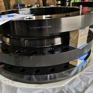
The ASME B16.47 flanges refer to large diameter pipe flanges manufactured in accordance with ASME B16.47, which covers pressure-temperature ratings, materials, dimensions, tolerances, marking, and testing for the flanges. These flanges can be provided in sizes NPS 26 through NPS 60 with rating class designations 75, 150, 300, 400, 600, and 900. NPS is the designation for nominal flange size. It is related to the reference nominal diameter, DN, used in international and other standards. For flange sizes covered in ASME B16.47, the relationship is DN = 25 × NPS. The standard specification states values in both SI metric and U.S. Customary units, except that diameter of bolts and flange bolt holes are expressed in inch units only.
ASME B16.47 Series A specifies flange dimensions for general use flanges, which are originated from MSS SP 44 and covering Class 150, Class 300, Class 400, Class 600, and Class 900. Series A and Series B are, in general, not interchangeable.
Materials and Manufacturing
Particularly, forged flanges, manufactured according to ASME B16.47 Series A or Series B, shall be manufactured as one piece in accordance with the applicable material specification. The forging process, either die forging or open-die forging, is a compressive plastic hot working operation that consolidates the material to flow in the direction most favorable for resisting the stresses encountered in service.
| Group No. | Forgings | Castings | Plates |
| 1.1 | A105 | A216 Gr.WCB | A515 Gr.70 |
| 1.1 | A350 Gr.LF2 | - | A516 Gr.70 |
| 1.1 | - | - | A537 Cl.1 |
| 1.1 | A350 Gr.LF6 Cl.1 | - | - |
| 1.1 | A350 Gr.LF3 | - | - |
| 1.2 | - | A216 Gr.WCC | - |
| 1.2 | - | A352 Gr.LCC | - |
| 1.2 | A350 Gr.LF6 Cl2 | - | - |
| 1.2 | - | A352 Gr.LC2 | A203 Gr.B |
| 1.2 | - | A352 Gr.LC3 | A203 Gr.E |
| 1.3 | - | A352 Gr.LCB | A515 Gr.65 |
| 1.3 | - | - | A516 Gr.65 |
| 1.3 | - | - | A203 Gr.A |
| 1.3 | - | - | A203 Gr.D |
| 1.3 | - | A217 Gr.WC1 | - |
| 1.3 | - | A352 Gr.LC1 | - |
Major Materials Chemical Composition and Mechanical Properties
ASTM A105 Chemical Composition (%)
| Steel Class | C max | Si | Mn | P max | S max | Ni max | Cr max | Mo max | N |
| A105 | 0.35 | 0.10-0.35 | 0.60-1.05 | 0.035 | 0.040 | 0.40 | 0.30 | 0.12 |
ASTM A105 Mechanical Properties
| Steel Class | Tensile Strength | Yield Strength | Elongation in 2in | Reduction of area | Solutioning Temperature | Quenching Cool |
| min | min | min | min | min | below | |
| A105 | 485 | 250 | 22 | 30 |
ASTM A350 Flange Materials Chemical Composition
| Grade | Composition, % | ||||||
| Grade LF1 | Grade LF2 | Grade LF3 | Grade LF5 | Grade LF6 | Grade LF9 | Grade LF787 | |
| C (max) | 0.30 | 0.30 | 0.20 | 0.20-0.35 | 0.22 | 0.20 | 0.70 |
| Mn | 0.60-1.35 | 0.60-1.35 | 0.90max | 0.60-1.35 | 1.15-1.50 | 0.40-1.06 | 0.40-0.70 |
| P | 0.035 | 0.035 | 0.035 | 0.035 | 0.025 | 0.035 | 0.025 |
| S (max) | 0.04 | 0.04 | 0.04 | 0.04 | 0.025 | 0.04 | 0.025 |
| SiA | 0.15-0.30 | 0.15-0.30 | 0.20-0.35 | 0.20-0.35 | 0.15-0.30 | ﹍ | 0.40 max |
| Ni | 0.40 maxB | 0.40 maxB | 3.30-3.70 | 1.0-2.0 | 0.40 maxB | 1.60-2.24 | 0.70-1.0 |
| Cr | 0.30 maxB, C | 0.30 maxB, C | 0.30 maxC | 0.30 maxC | 0.30 maxB, C | 0.30 maxC | 0.60-0.90 |
| Mo | 0.12 maxB, C | 0.12 maxB, C | 0.12 maxC | 0.12 maxC | 0.12 maxB, C | 0.12 maxC | 0.15-0.25 |
| Cu | 0.40 maxB | 0.40 maxB | 0.40 max | 0.40 max | 0.40 maxB | 0.75-1.25 | 1.0-1.3 |
| Cb | 0.02 maxD | 0.02 maxD | 0.02 max | 0.02 max | 0.02 max | 0.02 max | 0.02 min |
| V | 0.08 max | 0.08 max | 0.03 max | 0.03 max | 0.04-0.11 | 0.03 max | 0.03 max |
| N | ﹍ | ﹍ | ﹍ | ﹍ | 0.01-0.03 | ﹍ | ﹍ |
A When vacuum carbon-deoxidation is required by Supplementary Requirement S4, the Silicon content shall be o.12%
B The sum of copper, Nickel, chromium, vanadium and molybdenum shall not exceed 1.00% on heat analysis
C The sum of chromium and molybdenum shall not exceed 0.32% on heat analysis.
D By agreement, the limit for columbium may be increased up to 0.05% on heat analysis and 0.06% on product analysis.
ASTM A350 Mechanical Properties
| Grade/Class | Tensile Strength | Yield Strength min | Elongation, min | Hardness, max | ||
| ksi | MPa | ksi | MPa | % | HBW | |
| LFI CL1 | 60-85 | 415-585 | 30 | 205 | 25 | 197 |
| LF5 CL1 | 60-85 | 415-585 | 30 | 205 | 25 | 197 |
| LF2 CL1 | 70-95 | 485-655 | 36 | 250 | 22 | 197 |
| LF2 CL2 | 70-95 | 485-655 | 36 | 250 | 22 | 197 |
| LF3 CL1 | 70-95 | 485-655 | 37.5 | 260 | 22 | 197 |
| LF3 CL2 | 70-95 | 485-655 | 37.5 | 260 | 22 | 197 |
| LF5 CL2 | 70-95 | 485-655 | 37.5 | 260 | 22 | 197 |
| LF6 CL1 | 66-91 | 455-630 | 52 | 360 | 22 | 197 |
| LF6 CL2 | 75-100 | 515-690 | 60 | 415 | 20 | 197 |
| LF6 CL3 | 75-100 | 515-690 | 60 | 415 | 20 | 197 |
| LF9 | 63-88 | 435-605 | 46 | 315 | 25 | 197 |
| LF787 CL2 | 65-85 | 450-585 | 55 | 380 | 20 | 197 |
| LF787 CL3 | 75-95 | 515-655 | 65 | 450 | 20 | 197 |
ASME B16.47 Series A Flange Dimensions by Class (mm)

ANSI B16.47 Series A Flange Dimensions - Class 150 (mm)
| NPS Inch | Outside Dia. | Dia. of bolt Circle | Dia. of RF | Dia. of Hub | Dia. of Hub Top | Min Thickness | Y | Bolt Holes | r | |||
| D | K | G | X | A | TBL | TWN | Numbers | D Inch | L Inch | |||
| 26" | 870 | 806.4 | 749 | 676 | 660.4 | 66.7 | 66.7 | 119 | 24 | 1-3/8 | 1-1/4 | 10 |
| 28" | 925 | 863.6 | 800 | 727 | 711.2 | 69.9 | 69.9 | 124 | 28 | 1-3/8 | 1-1/4 | 11 |
| 30" | 985 | 914.4 | 857 | 781 | 762.0 | 73.1 | 73.1 | 135 | 28 | 1-3/8 | 1-1/4 | 11 |
| 32" | 1060 | 977.9 | 914 | 832 | 812.8 | 79.4 | 79.4 | 143 | 28 | 1-5/8 | 1-1/2 | 11 |
| 34" | 1110 | 1028.7 | 965 | 883 | 863.6 | 81.0 | 81.0 | 148 | 32 | 1-5/8 | 1-1/2 | 13 |
| 36" | 1170 | 1085.8 | 1022 | 933 | 914.4 | 88.9 | 88.9 | 156 | 32 | 1-5/8 | 1-1/2 | 13 |
| 38" | 1240 | 1149.4 | 1073 | 991 | 965.2 | 85.8 | 85.8 | 156 | 32 | 1-5/8 | 1-1/2 | 13 |
| 40" | 1290 | 1200.2 | 1124 | 1041 | 1016.0 | 88.9 | 88.9 | 162 | 36 | 1-5/8 | 1-1/2 | 13 |
| 42" | 1345 | 1257.3 | 1194 | 1092 | 1066.8 | 95.3 | 95.3 | 170 | 36 | 1-5/8 | 1-1/2 | 13 |
| 44" | 1405 | 1314.4 | 1245 | 1143 | 1117.6 | 100.1 | 100.1 | 176 | 40 | 1-5/8 | 1-1/2 | 13 |
| 46" | 1455 | 1365.2 | 1295 | 1197 | 1168.4 | 101.6 | 101.6 | 184 | 40 | 1-5/8 | 1-1/2 | 13 |
| 48" | 1510 | 1422.4 | 1359 | 1248 | 1219.2 | 106.4 | 106.4 | 191 | 44 | 1-5/8 | 1-1/2 | 13 |
| 50" | 1570 | 1479.6 | 1410 | 1302 | 1270.0 | 109.6 | 109.6 | 202 | 44 | 1-7/8 | 1-3/4 | 13 |
| 52" | 1625 | 1536.7 | 1461 | 1353 | 1320.8 | 114.3 | 114.3 | 208 | 44 | 1-7/8 | 1-3/4 | 13 |
| 54" | 1685 | 1593.8 | 1511 | 1403 | 1371.6 | 119.1 | 119.1 | 214 | 44 | 1-7/8 | 1-3/4 | 13 |
| 56" | 1745 | 1651.0 | 1575 | 1457 | 1422.4 | 122.3 | 122.3 | 227 | 48 | 1-7/8 | 1-3/4 | 13 |
| 58" | 1805 | 1708.2 | 1626 | 1508 | 1473.2 | 127.0 | 127.0 | 233 | 48 | 1-7/8 | 1-3/4 | 13 |
| 60" | 1855 | 1759.0 | 1676 | 1559 | 1524.0 | 130.2 | 130.2 | 238 | 52 | 1-7/8 | 1-3/4 | 13 |
ANSI B16.47 Series A Flange Dimensions – Class 300 (mm)
| NPS Inch | Outside Dia. | Dia. of bolt Circle | Dia. of RF | Dia. of Hub | Dia. of Hub Top | Min Thickness | Y | Bolt Holes | r | |||
| D | K | G | X | A | TBL | TWN | Numbers | D Inch | L Inch | |||
| 26" | 970 | 876.3 | 749 | 721 | 660.4 | 82.6 | 77.8 | 183 | 28 | 1-3/4 | 1-5/8 | 10 |
| 28" | 1035 | 939.8 | 800 | 775 | 711.2 | 88.9 | 84.2 | 195 | 28 | 1-3/4 | 1-5/8 | 11 |
| 30" | 1090 | 997.0 | 857 | 827 | 762.0 | 93.7 | 90.5 | 208 | 28 | 1-7/8 | 1-3/4 | 11 |
| 32" | 1150 | 1054.1 | 914 | 881 | 812.8 | 98.5 | 96.9 | 221 | 28 | 2 | 1-7/8 | 11 |
| 34" | 1205 | 1104.9 | 965 | 937 | 863.6 | 103.2 | 100.1 | 230 | 28 | 2 | 1-7/8 | 13 |
| 36" | 1270 | 1168.4 | 1022 | 991 | 914.4 | 109.6 | 103.2 | 240 | 32 | 2-1/8 | 2 | 13 |
| 38" | 1170 | 1092.2 | 1029 | 994 | 965.2 | 106.4 | 106.4 | 179 | 32 | 1-5/8 | 1-1/2 | 13 |
| 40" | 1240 | 1155.7 | 1086 | 1048 | 1016.0 | 112.8 | 112.8 | 192 | 32 | 1-3/4 | 1-5/8 | 13 |
| 42" | 1290 | 1206.5 | 1137 | 1099 | 1066.8 | 117.5 | 117.5 | 198 | 32 | 1-3/4 | 1-5/8 | 13 |
| 44" | 1355 | 1263.6 | 1194 | 1149 | 1117.6 | 122.3 | 122.3 | 205 | 32 | 1-7/8 | 1-3/4 | 13 |
| 46" | 1415 | 1320.8 | 1245 | 1203 | 1168.4 | 127.0 | 127.0 | 214 | 28 | 2 | 1-7/8 | 13 |
| 48" | 1465 | 1371.6 | 1302 | 1254 | 1219.2 | 131.8 | 131.8 | 222 | 32 | 2 | 1-7/8 | 13 |
| 50" | 1530 | 1428.8 | 1359 | 1305 | 1270.0 | 138.2 | 138.2 | 230 | 32 | 2-1/8 | 2 | 13 |
| 52" | 1580 | 1479.6 | 1410 | 1356 | 1320.8 | 142.9 | 142.9 | 237 | 32 | 2-1/8 | 2 | 13 |
| 54" | 1660 | 1549.4 | 1467 | 1410 | 1371.6 | 150.9 | 150.9 | 251 | 28 | 2-3/8 | 2-1/4 | 13 |
| 56" | 1710 | 1600.2 | 1518 | 1464 | 1422.4 | 152.4 | 152.4 | 259 | 28 | 2-3/8 | 2-1/4 | 13 |
| 58" | 1760 | 1651.0 | 1575 | 1514 | 1473.2 | 157.2 | 157.2 | 265 | 32 | 2-3/8 | 2-1/4 | 13 |
| 60" | 1810 | 1701.8 | 1626 | 1565 | 1524.0 | 162.0 | 162.0 | 271 | 32 | 2-3/8 | 2-1/4 | 13 |
ANSI B16.47 Series A Flange Dimensions - Class 400 (mm)
| NPS Inch | Outside Dia. | Dia. of bolt Circle | Dia. of RF | Dia. of Hub | Dia. of Hub Top | Min Thickness | Y | Bolt Holes | r | |||
| D | K | G | X | A | TBL | TWN | Numbers | D Inch | L Inch | |||
| 26" | 970 | 876.3 | 749 | 727 | 660.4 | 98.5 | 88.9 | 194 | 28 | 1-7/8 | 1-3/4 | 11 |
| 28" | 1035 | 939.8 | 800 | 783 | 711.2 | 104.8 | 95.3 | 206 | 28 | 2 | 1-7/8 | 13 |
| 30" | 1090 | 997.0 | 857 | 837 | 762.0 | 111.2 | 101.6 | 219 | 28 | 2-1/8 | 2 | 13 |
| 32" | 1150 | 1054.1 | 914 | 889 | 812.8 | 115.9 | 108.0 | 232 | 28 | 2-1/8 | 2 | 13 |
| 34" | 1205 | 1104.9 | 965 | 945 | 863.6 | 122.3 | 111.2 | 241 | 28 | 2-1/8 | 2 | 14 |
| 36" | 1270 | 1168.4 | 1022 | 1000 | 914.4 | 128.6 | 114.3 | 251 | 32 | 2-1/8 | 2 | 14 |
| 38" | 1205 | 1117.6 | 1035 | 1003 | 965.2 | 123.9 | 123.9 | 206 | 32 | 1-7/8 | 1-3/4 | 14 |
| 40" | 1270 | 1174.6 | 1092 | 1054 | 1016.0 | 130.2 | 130.2 | 216 | 32 | 2 | 1-7/8 | 14 |
| 42" | 1320 | 1225.6 | 1143 | 1108 | 1066.8 | 133.4 | 133.4 | 224 | 32 | 2 | 1-7/8 | 14 |
| 44" | 1385 | 1282.7 | 1200 | 1159 | 1117.6 | 139.7 | 139.7 | 233 | 32 | 2-1/8 | 2 | 14 |
| 46" | 1440 | 1339.8 | 1257 | 1213 | 1168.4 | 146.1 | 146.1 | 244 | 36 | 2-1/8 | 2 | 14 |
| 48" | 1510 | 1403.4 | 1308 | 1267 | 1219.2 | 152.4 | 152.4 | 257 | 28 | 2-3/8 | 2-1/4 | 14 |
| 50" | 1570 | 1460.5 | 1362 | 1321 | 1270.0 | 158.8 | 157.2 | 268 | 32 | 2-3/8 | 2-1/4 | 14 |
| 52" | 1620 | 1511.3 | 1413 | 1372 | 1320.8 | 163.6 | 162.0 | 276 | 32 | 2-3/8 | 2-1/4 | 14 |
| 54" | 1700 | 1581.2 | 1470 | 1426 | 1371.6 | 171.5 | 169.9 | 289 | 28 | 2-5/8 | 2-1/2 | 14 |
| 56" | 1755 | 1632.0 | 1527 | 1480 | 1422.4 | 176.3 | 174.7 | 298 | 32 | 2-5/8 | 2-1/2 | 14 |
| 58" | 1805 | 1682.8 | 1578 | 1530 | 1473.2 | 181.0 | 177.8 | 306 | 32 | 2-5/8 | 2-1/2 | 14 |
| 60" | 1885 | 1752.6 | 1635 | 1584 | 1524.0 | 189.0 | 185.8 | 319 | 32 | 2-7/8 | 2-3/4 | 14 |
ANSI B16.47 Series A Flange Dimensions - Class 600 (mm)
| NPS Inch | Outside Dia. | Dia. of bolt Circle | Dia. of RF | Dia. of Hub | Dia. of Hub Top | Min Thickness | Y | Bolt Holes | r | |||
| D | K | G | X | A | TBL | TWN | Numbers | D Inch | L Inch | |||
| 26" | 1015 | 914.4 | 749 | 748 | 660.4 | 125.5 | 108.0 | 222 | 28 | 2 | 1-7/8 | 13 |
| 28" | 1075 | 965.2 | 800 | 803 | 711.2 | 131.8 | 111.2 | 235 | 28 | 2-1/8 | 2 | 13 |
| 30" | 1130 | 1022.4 | 857 | 862 | 762.0 | 139.7 | 114.3 | 248 | 28 | 2-1/8 | 2 | 13 |
| 32" | 1195 | 1079.5 | 914 | 918 | 812.8 | 147.7 | 117.5 | 260 | 28 | 2-3/8 | 2-1/4 | 13 |
| 34" | 1245 | 1130.3 | 965 | 973 | 863.6 | 154.0 | 120.7 | 270 | 28 | 2-3/8 | 2-1/4 | 14 |
| 36" | 1315 | 1193.8 | 1022 | 1032 | 914.4 | 162.0 | 123.9 | 283 | 28 | 2-5/8 | 2-1/2 | 14 |
| 38" | 1270 | 1162.0 | 1054 | 1022 | 965.2 | 155.0 | 152.4 | 254 | 28 | 2-3/8 | 2-1/4 | 14 |
| 40" | 1320 | 1212.8 | 1111 | 1073 | 1016.0 | 162.0 | 158.8 | 264 | 32 | 2-3/8 | 2-1/4 | 14 |
| 42" | 1405 | 1282.7 | 1168 | 1127 | 1066.8 | 171.5 | 168.3 | 279 | 28 | 2-5/8 | 2-1/2 | 14 |
| 44" | 1455 | 1333.5 | 1226 | 1181 | 1117.6 | 177.8 | 173.1 | 289 | 32 | 2-5/8 | 2-1/2 | 14 |
| 46" | 1510 | 1390.6 | 1276 | 1235 | 1168.4 | 185.8 | 179.4 | 300 | 32 | 2-5/8 | 2-1/2 | 14 |
| 48" | 1595 | 1460.5 | 1334 | 1289 | 1219.2 | 195.3 | 189.0 | 316 | 32 | 2-7/8 | 2-3/4 | 14 |
| 50" | 1670 | 1524.0 | 1384 | 1343 | 1270.0 | 203.2 | 195.9 | 329 | 28 | 3-1/8 | 3 | 14 |
| 52" | 1720 | 1574.8 | 1435 | 1394 | 1320.8 | 209.6 | 203.2 | 337 | 32 | 3-1/8 | 3 | 14 |
| 54" | 1780 | 1632.0 | 1492 | 1448 | 1371.6 | 217.5 | 209.6 | 349 | 32 | 3-1/8 | 3 | 14 |
| 56" | 1855 | 1695.4 | 1543 | 1502 | 1422.4 | 225.5 | 217.5 | 362 | 32 | 3-3/8 | 3-1/4 | 16 |
| 58" | 1905 | 1746.2 | 1600 | 1553 | 1473.2 | 231.8 | 222.3 | 370 | 32 | 3-3/8 | 3-1/4 | 16 |
| 60" | 1995 | 1822.4 | 1657 | 1610 | 1524.0 | 242.9 | 233.4 | 389 | 28 | 3-5/8 | 3-1/2 | 17 |
ANSI B16.47 Series A Flange Dimensions - Class 900 (mm)
| NPS Inch | Outside Dia. | Dia. of bolt Circle | Dia. of RF | Dia. of Hub | Dia. of Hub Top | Min Thickness | Y | Bolt Holes | r | |||
| D | K | G | X | A | TBL | TWN | Numbers | D Inch | L Inch | |||
| 26" | 1085 | 952.5 | 749 | 775 | 660.4 | 160.4 | 139.7 | 286 | 20 | 2-7/8 | 2-3/4 | 11 |
| 28" | 1170 | 1022.4 | 800 | 832 | 711.2 | 171.5 | 142.9 | 298 | 20 | 3-1/8 | 3 | 13 |
| 30" | 1230 | 1085.8 | 857 | 889 | 762.0 | 182.6 | 149.3 | 311 | 20 | 3-1/8 | 3 | 13 |
| 32" | 1315 | 1155.7 | 914 | 946 | 812.8 | 193.7 | 158.8 | 330 | 20 | 3-3/8 | 3-1/4 | 13 |
| 34" | 1395 | 1225.6 | 965 | 1006 | 863.6 | 204.8 | 165.1 | 349 | 20 | 3-5/8 | 3-1/2 | 14 |
| 36" | 1460 | 1289.0 | 1022 | 1064 | 914.4 | 214.4 | 171.5 | 362 | 20 | 3-5/8 | 3-1/2 | 14 |
| 38" | 1460 | 1289.0 | 1099 | 1073 | 965.2 | 215.9 | 190.5 | 352 | 20 | 3-5/8 | 3-1/2 | 19 |
| 40" | 1510 | 1339.8 | 1162 | 1127 | 1016.0 | 223.9 | 196.9 | 364 | 24 | 3-5/8 | 3-1/2 | 21 |
| 42" | 1560 | 1390.6 | 1213 | 1176 | 1066.8 | 231.8 | 206.4 | 371 | 24 | 3-5/8 | 3-1/2 | 21 |
| 44" | 1650 | 1463.7 | 1270 | 1235 | 1117.6 | 242.9 | 214.4 | 391 | 24 | 3-7/8 | 3-3/4 | 22 |
| 46" | 1735 | 1536.7 | 1334 | 1292 | 1168.4 | 255.6 | 225.5 | 411 | 24 | 4-1/8 | 4 | 22 |
| 48" | 1785 | 1587.5 | 1384 | 1343 | 1219.2 | 263.6 | 233.4 | 419 | 24 | 4-1/8 | 4 | 24 |
| 50" | - | - | - | - | - | - | - | - | - | - | - | - |
| 52" | - | - | - | - | - | - | - | - | - | - | - | - |
| 54" | - | - | - | - | - | - | - | - | - | - | - | - |
| 56" | - | - | - | - | - | - | - | - | - | - | - | - |
| 58" | - | - | - | - | - | - | - | - | - | - | - | - |
| 60" | - | - | - | - | - | - | - | - | - | - | - | - |


ASME B16.47 Carbon Steel Flange Series A 26 Inch Welding Neck Blind Class 150
Inquiry Cart
0