
Add to Cart
【Transistor tester control 】
1.The tester is controlled by a rotary encoder switch.
2.The rotary encoder switch can be operated in a total of 6 ways,
short press, long press, left turn, right turn, press and hold left
turn, press and hold right turn.
3.A short press in the off position turns the power on and starts
the test.
4.After a test has been completed, if no device is detected. Press
and hold the switch or rotate the switch left or right to enter the
function menu. Once in the function menu, the left or right switch
can be rotated up or down through the menu items, to enter a
particular function item, press the switch once short. When it is
necessary to exit from a certain function, then press the switch
long.
Test Devices
The tester has 3 test points, TP1, TP2 and TP3, which are
distributed in the test stand as follows
On the right hand side of the test stand are the test positions for
the SMD components, with the numbers 1,2,3, each representing TP1,
TP2 and TP3 respectively.
When testing components with only 2 pins, the pins are not divided
into test order, 2 pins are chosen for any 2 test points, and the
pins of 3-pin devices are placed in three test points, in no
particular order. After the test, the tester automatically
recognises the pin name of the component, the test point where it
is located and displays it on the screen.
When testing components with only 2 pins, if two test points are
used, TP1 and TP3, the tester automatically enters continuous test
mode after the test is completed, so that the components on TP1 and
TP3 can be measured continuously and simultaneously without having
to press the switch again. If "TP1 and TP2" or "TP2 and TP3" are
used, only one test is performed. To test again, press the switch
once.
Note:
Before testing the capacitor, discharge the capacitor before inserting it into the test holder for measurement, otherwise there is a risk of damaging the tester's microcontroller.
1,Calibration
The tester calibration is used to eliminate errors in its own
components, making the final test results more accurate.
Calibration is divided into quick calibration and full function
calibration.
The operation method for quick calibration: short the three test
points TP1, TP2 and TP3 with wires and then press the test button
while watching the screen. The screen colour will change to white
text on a black background. After the prompt message "Selftest
mode...? ", press the test button to enter the fast calibration
process; if, after the message "Selftest mode...? If no button is
pressed within 2 seconds after the message "Selftest mode...", the
normal test process is carried out and the resistance values of the
three test points TP1, TP2 and TP3 are displayed at the end. After
entering the quick calibration process, some data will appear on
the screen, ignore it. Wait until a flashing string appears on the
screen
After "isolate Probes!", remove the shorted TP1, TP2 and TP3 leads.
The quick calibration is complete until the string "Test End"
appears on the screen. When calibrating for the first time, use the
full function calibration method.
The full function calibration is accessed from the function menu
and requires an additional 220nf capacitor. Full function
calibration performs a more comprehensive calibration process and
can take longer. Once in the function menu, turn the test button to
the menu item "Selftest", then press the test button to enter the
full function calibration process, which starts with the flashing
string "short Probes! When the flashing string "isolate Probes!"
appears on the screen, remove the wires from the three test points
and continue to wait for the calibration process to proceed, when
the string "1-||- 3 > 100nf", install the prepared 220nf
capacitors on test points TP1 and TP3. Wait until the screen says
"Test End" and the fully functional calibration process is
complete.
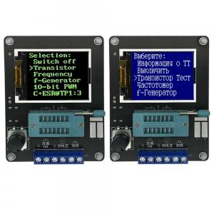
2. Function menu
2.1 Switch off
2.2 Transistor
2.3 Frequency
Measures the frequency. Press and hold the test button to exit the
frequency measurement function. The frequency measurement range is
from 1 Hz to more than 1 MHz, when the measured frequency is below
25 KHz, the period is displayed
2.4 f-Generator
Square wave generator with multiple square wave frequencies
selectable, turn the test button left or right to switch between
different square wave frequencies, long press the test button to
exit the square wave generator.
2.5 10-bit PWM
Pulse generator, left or right turn the test button to adjust the
duty cycle of the pulse from 1% - 99%. Press and hold the test
button to exit the pulse generator.
2.6 C+ESR@TP1:3
Capacitance in-line measurement function, two wires can be led from
TP1 and TP3 to measure the capacitance value and ESR of a 2uF-50mF
capacitor in-line, note that the capacitor under test needs to be
completely discharged before the test, if the measurement is
in-line, the circuit where the capacitor is located needs to be
completely disconnected before the test can be carried out.
2.7
Resistance continuous measurement method, constantly test the
resistance value and inductance value installed on TP1 and TP3. The
inductance is measured only when the resistance under test is less
than 2100 ohms, and the inductance is measured from 0.01mH to 20H .
Press and hold the test button to exit.
2.8 1-||-3
The capacitance continuous measurement method continuously tests
the capacitance values mounted on TP1 and TP3. For small
capacitance capacitors, the capacitance values can only be measured
in this test method. The equivalent series resistance (ESR) value
is measured for capacitors greater than 90nF with a resolution of
0.01Ω. capacitors above 5000pF show their voltage drop rate after
charging.
2.9 DS18B20 Russian version without this function
The DS18B20 is a temperature sensor that uses a single bus
communication method to transfer data and has the same package as
the triode (TO-92), the diagram below shows the pinout of the
DS18B20.
After entering the DS18B20 test function, the second line of the
display shows the connection between the test holder and the
DS18B20, "1=GND 2=DQ 3=VDD", indicating that TP1 is connected to
the GND of the DS18B20, TP2 is connected to the DQ of the DS18B20
and TP3 is connected to the VDD of the DS18B20. The tester does not
automatically recognise the DS18B20, so you must follow the
instructions in the second line to install the DS18B20.
The tester can read the 12-digit temperature result measured by the
DS18B20 and display it in the third line as the corresponding
Celsius temperature value with a resolution of 0.0625°C.
Scratchpad: The tester reads the contents of the 8 internal memory
cells of the DS18B20 plus the last byte of the CRC check value. 9
bytes in total.
Scratchpad BYTE
TEMPERATURE LSB 0
TEMPERATURE MSB 1
TH/USER BYTE 1 2
TL/USER BYTE 2 3
CONFIG 4
RESERVED 5
RESERVED 6
RESERVED 7
CRC 8
For example, if the value read at one time is Scratchpad:
EC014B467FFF0C102A then the relationship is as follows
Scratchpad Value BYTE
TEMPERATURE LSB EC 0
TEMPERATURE MSB 01 1
TH/USER BYTE 1 4B 2
TL/USER BYTE 2 46 3
CONFIG 7F 4
RESERVED FF 5
RESERVED 0C 6
RESERVED 10 7
CRC 2A 8
64-bit ROM: The globally unique device ID of each DS18B20 read by
the tester, which is 64 bits long. It is divided into 3 parts.
For example, the 64-bit ROM read by a DS18B20 is
64-bit ROM: 28FF4D58361604A1
then there is
8-BIT FAMILY CODE 28
48-BIT SERIAL NUMBER 041636584DFF
8-BIT CRC CODE A1
Note: All parts are in hexadecimal, except for the temperature
value (TEMP), which is in decimal.
The temperature measurement range of the DS18B20 is from -55°C -
125°C. Press and hold the test button to exit this function.
2.10 C(uF)-correction
This function is used to correct the measured value of the
high-capacity capacitance, which is set to 0% by default. This
means that there is no correction and is set from -0.2% - 8%. A
positive value will reduce the measured value of the capacitor and
a negative value will increase the measured value of the capacitor.
After setting, press and hold the test button to exit.
2.11 IR_Decoder Russian version without this function
This function requires the use of an 1838 integrated IR receiver
(pulse type), after entering this function, observe the second line
of the prompt on the display which shows the string ""1=DOUT 2=GND
3=VCC", the meaning of the string indicates the 3 test points on
the tester and the IR receiver. The string indicates the connection
between the 3 test points on the tester and the IR receiver head,
which must be connected in strict accordance with the instructions.
Only one IR receiver can be left empty or correctly installed in
the test stand, no other components can be placed in it, and the
test points must not be shorted with wires. This is to avoid
unpredictable faults. The diagram below shows the mounting
orientation of the example IR receiver head.
TP1 is connected to the DOUT pin of the IR receiver head, TP2 to
GND and TP3 to VCC.
The IR remote control decoding function supports two IR remote
control coding formats.
Format I
Format 2
The above two formats are roughly the same, the difference lies in
the length of the boot code. Format 1 is 9MS and format 2 is 4.5MS.
The IR remote control decoding function uses uPD6121 for format one
and TC9012 for format two respectively.
Operating Instructions
The IR remote control decoding function can only be accessed from
the function menu. Before entering the IR remote control decoding
function, there must not be any components on the test stand or on
the square wave output terminals. Enter the IR remote control
decoding function and wait until the display shows the "standing
by..." After the string "standing by..." appears on the display,
put the integrated IR receiver head into the test base and lock it
in place. The remote control can then be pointed at the IR receiver
head and fired. If the code used for the remote control is
recognised. The third line will show a string of characters
">>>>>>>>>>>" indicating a
successful decode and the fourth line will show the code format
used for the remote control. The fifth line shows the first byte of
the user code (user code1) and the sixth line shows the second byte
of the user code (user code2). The seventh line shows the data code
(data) and the data inverse code (~data).
(All values of the IR decoder function are in hexadecimal format.
The IR decoding function only supports single key mode, not
continuous mode. When testing this function, I found that several
TV remote controls used for testing were TC9012, the small Mp3
remote control was uPD6121, and the air conditioner remote control
was not recognized :-(.) Due to the limitations, no further testing
could be done.
To exit from this function, remove the receiver head from the test
holder and then press and hold the rotary encoder switch to exit.
2.11 IR_Encoder Russian version without this function
The IR remote control encoder function requires an infrared LED.
The tester can control this infrared LED and thus implement an
infrared remote control function. As the tester can only provide a
maximum drive current of around 6mA, the control distance cannot be
compared to that of a normal infrared remote control. With the
infrared receiver head aligned to transmit, it is probably within
2m.
The IR remote control encoding supports two formats, the same as
the IR remote control decoding format described earlier. The
uPD6121 is also used to indicate format one and the TC9012 to
indicate format two.
Operating instructions
The IR remote control coding function can only be accessed from the
function menu. Before entering the IR remote control coding
function, there must not be any components on the test stand or on
the square wave output terminals. After entering the infrared
remote control coding function, connect an infrared LED to the
square wave output terminal, with the negative terminal of the
infrared LED connected to earth and the positive terminal connected
to the output. The positive and negative terminals of the infrared
LED can be extended using wires to facilitate operation. The long
leg of the infrared LED is positive and the short leg is negative.
In the leftmost column of the display is a ">" symbol indicating
which parameter is currently being set. A short press on the test
button toggles the ">" between the various setting items. The
second line, "protocol", sets the encoding format to be used.
Rotating the test button left and right switches between "uPD6121"
and "TC9012".
The third and fourth lines "user code1" and "user code2" set the
first and second bytes of the user code, which can be decreased in
steps of 1 by rotating the test button left and increased in steps
of 1 by rotating the test button right.
The fifth line sets the data code, which can be decreased by 1 for
the left-hand test button and increased by 1 for the right-hand
test button. The data inverse code is calculated automatically from
the data code and cannot be set manually.
When setting the value of the user code and data code, in addition
to changing the value in units of 1 by rotating the test button
left and right, the value can also be increased in units of 0x10 by
pressing and holding the test button for a long time, but not too
long, if too long, the function is withdrawn. This is not easy to
grasp at first. The sixth line is the emit control "emit:". By
moving the ">" symbol to this line, the test button can be
rotated left and right to emit infrared light according to the data
set above. When you turn the test switch, you will see a quick
flash of the "->" symbol. This indicates that the data has been
emitted once.