Add to Cart
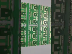
Double-sided FPC thick copper PCB board
PCB quick details:
Product category: FPC special process board
Basic parameters: application: manipulator test line
Type: double-sided FPC thick copper plate
Size: 270mm * 66mm
Tolerance: ± 0.03mm
Finished product thickness: 0.3mm
Reinforcement: 0.5mm FR4
Surface treatment: gold
Cost Effective Flex & Rigid-Flex PCBs
When it comes to our flex and rigid-flex products, we offer a
variety of cost effective solutions and capabilities that include
single or double sided circuitry to higher technology multilayer
designs up to 20 layers. From selecting the best functional
configuration, to choosing the proper connectors or components, we
will help you meet or exceed all your applications requirements.
Our flex and rigid-flex PCBs are manufactured for various
applications in the medical, military, aerospace, and portable
devices industries.
Our engineering team can assist you from early design stages of
your application all the way to end product production for all your
flex and rigid-flex circuit needs.
Flexible PCB Design Considerations
Proper design is crucial for manufacturing reliable,
high-performing flex PCBs. Designers must account for the dynamic
nature of flex circuits and make considerations for:
Bend Radius – The minimum bend radius determines the flexibility
and durability. Inside bend radii down to 0.1mm can be achieved
with optimal materials and stackup.
Board Stiffness – Polyimide films provide good flexural endurance
but also dimensional stability. Selective stiffening elements like
cover layers are used when needed.
Thermal Management – Large copper planes dissipate heat
efficiently. But flexing actions require thermal mitigation
techniques like thermal reliefs.
High-Frequency Layout – Controlled impedance traces, ground planes,
and vias enable flex PCBs to operate at high frequencies for RF and
digital signals.
Component Selection – Low-profile SMT components withstand flexing
and minimize thickness. Avoid rigid connectors, opting for
flex-tail or ribbon cable connections.
Attachment Methods – Soldering, conductive epoxy, and mechanical
fastening attach components reliably. Adhesive selection is also
critical.
At ONESEINE PCB, our engineering team provides flex PCB design
reviews and recommendations to identify opportunities for
optimization. We have experience designing flex circuits for
dynamic applications across industries.
By partnering with us early in the design process, we can help
assess manufacturability, troubleshoot any issues with the planned
construction, and ensure your flex PCB design is optimized for
cost-effective fabrication and assembly.
Flexible PCB Assembly Techniques
Assembly of components onto flex PCBs requires specialized
techniques compared to standard rigid PCB assembly. ONESEINE PCB
has developed proven assembly processes to mount components onto
flex circuits reliably.
SMT assembly is suitable for lower component counts, allowing
pick-and-place and reflow soldering of chip components. For higher
densities, manual assembly may be required.
Component attachment methods include:
Solder joints – For heat-resistant components. Care is needed to
avoid base film damage.
Conductive epoxy – Provides strong mechanical bonds with electrical
connection.
Mechanical fasteners – Standoffs, screws, and clamps provide solid
mounting.
Pressure-sensitive adhesives – Adhere components while allowing
rework/repair.
We select adhesives optimized for flexibility, peel strength, tear
resistance, and operating temperatures. Adhesive curing methods
include heat, pressure, ultrasonic energy, and humidity.
Flex PCB rework and repair present challenges due to the
sensitivity of polyimide films. We utilize specialized systems and
processes for component removal and replacement without circuit
damage.
Our experienced PCB assembly technicians are trained on the unique
requirements of flex PCB assembly. We’ve optimized our assembly
processes for high yields, maximum uptime, and fast turnaround.
By leveraging our flex PCB assembly expertise, customers can
accelerate their hardware development schedules and move quickly
from PCB prototyping to mass production. We’re ready to discuss
your specific application requirements and determine the optimal
assembly process.
Flexible PCB Fabrication Process
Flex PCBs require specialized materials and processes compared to
standard rigid PCB boards. ONESEINE PCB utilizes cutting-edge
fabrication techniques to produce high-quality, reliable flex
circuits.
Polyimide is the most common base material used in flex PCB
fabrication. The high heat resistance, chemical stability, and
mechanical flexibility of polyimide films like DuPont’s Kapton make
them ideal substrates. We also use flexible PET films for certain
applications.
The circuitry layers are constructed using rolled annealed copper
laminated to the base film. Photolithographic patterning techniques
are used to etch the copper and generate trace geometries and
spaces. Flex PCBs are typically single-layer or multilayer with 2
to 12 metal layers separated by adhesive dielectric films.
Our flex PCB manufacturing capabilities support sophisticated flex
stackups. We produce double-sided flex using plated-through holes
and microvias for interlayer connections. For multilayer flex,
laser drilling forms high-density vias with diameters down to 50μm.
Compared to rigid PCB boards, flex PCB fabrication offers benefits
like:
Thinner overall construction for compact, lightweight circuits
Dynamic flexural capability for movable/shape-changing electronics
Improved high-frequency signal integrity at bends
Enhanced heat dissipation with heat-spreader copper layers
Fine line/space traces and spacing for high interconnect density
We utilize AOI and electrical testing throughout the fabrication
process to ensure quality standards are met. Coupon samples are
also tested for coating thickness, adhesion, solderability, and
other performance metrics.