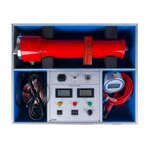
Add to Cart
Specification Technical Parameters | 60/2 | 60/3 | 80/10 | 120/2 | 120/3 | ||
The output voltage (kV) | 60 | 60 | 80 | 120 | 120 | ||
Output current (mA) | 2 | 3 | 10 | 2 | 3 | ||
Output Power (W) | 120 | 180 | 800 | 240 | 360 | ||
recharging current (mA) | 2 | 3 | 10 | 2 | 3 | ||
Control box weight(kg) | 2 | 2 | 2 | 2 | 2 | ||
Weight of spare cylinder(kg) | 2.5 | 2.5 | 4 | 4 | 4 | ||
Specifications of spare cylinder(mm) | Ф90 340 | Ф90 340 | Ф90 470 | Ф90 470 | Ф90 470 | ||
Voltage measurement error | 1% (full scale) ±1 character | ||||||
Current measurement error | 1% (full scale) ±1 character | ||||||
Overvoltage setting error | Overvoltage protection is set by dial, which is clear at a glance (accuracy ≤ 1.0%) | ||||||
0.75Switching error | High-precision 0.75UDC-1mA single-touch button (accuracy ≤1.0%) Best suited for zinc oxide arrester testing | ||||||
Ripple Factor | ≤0.5% | ||||||
Way of working | Intermittent use: rated load 30 minutes 1.1 times rated voltage use: 10 minutes | ||||||
working environment | Temperature: -10°C~+40°C | ||||||
Relative humidity: not more than 85% at room temperature of 25ºC (no condensation) | |||||||
Altitude: below 1500 meters | |||||||
With capacitive load | No limit on the capacitance of the test product | ||||||
Structural features | Electrical insulation voltage doubler | ||||||
Air insulation, no leakage concerns |
If you want to customize other voltage levels, please contact me
and I will help you solve any problems you encounter
Operation panel instructions
1. Digital ammeter: Digitally displays DC high voltage output
current.
2. Digital voltmeter: Digitally displays DC high voltage output
voltage.
3. Yellow lighted button: Valid when the red light is on. When the
yellow button is pressed, the yellow light is on, and the output
high voltage drops to 0.75 times the original value, and this state
is maintained for one minute. This function is specially used for
zinc oxide lightning arresters to quickly measure 0.75UDC-1mA.
Press the green button, the red and yellow lights are off, the high
voltage is cut off and exits the 0.75 times state.
4. Red lighted button: High voltage connection button, high voltage
indicator light. When the green light is on, press the red button,
the red light is on and the green light is off, indicating that the
high voltage circuit is connected, and the voltage can be increased
at this time. This button is only valid when the voltage adjustment
potentiometer returns to zero. If the red light is on and the green
light is still on when the red button is pressed, but the red light
goes out and the green light comes on when the button is released,
it means that the protection circuit in the machine has worked. At
this time, you must turn off the machine to check whether the
overvoltage setting dial switch setting is less than 5% of the full
scale and whether there are other faults before turning it on.
5. Green lighted button: The green light indicates that the power
is on and the high voltage is disconnected. When the red light is
on, press the green button, the red light goes out and the green
light comes on, and the high voltage circuit is cut off.
6. Power switch: Press this switch to the right, the power is on,
and the green light comes on. Otherwise, it is off.
7. Overvoltage setting dial switch: used to set the overvoltage
protection value. The overvoltage setting range is 0.05 to 1.2
times the rated voltage, and the value displayed by the dial switch
is in kV.
8. Voltage adjustment potentiometer: This potentiometer is a
multi-turn potentiometer. Clockwise rotation is for voltage
increase, and reverse rotation is for voltage reduction. This
potentiometer has an electronic zero position protection function,
so it must be returned to zero before voltage increase.
9. Power input socket: Connect the power cord provided with the
machine to the power input socket. (AC 220V ±10%, with built-in
fuse in the socket.)
10. Grounding terminal: This grounding terminal is connected to the
grounding terminal of the voltage multiplier and the grounding of
the test piece at one point and then connected to the grounding
grid.
11. Intermediate frequency and measurement cable quick connection
socket: used to connect the chassis to the voltage multiplier. When
connecting, just align the cable plug with the socket and push it
into place. When removing the wire, first move the outer clamp of
the cable plug backwards and apply a little force.
Technical Parameters
Features
1. The chassis adopts international universal chassis, which can be
used vertically or horizontally.
2. It adopts medium frequency voltage doubler circuit, applies PWM
pulse width modulation technology and high-power IGBT devices.
3. It adopts large voltage feedback, with high output voltage
stability and small ripple coefficient ≤1%.
4. Full range smooth voltage regulation, good voltage regulation
fineness, regulation accuracy ≤0.5%, stability ≤1%, voltage and
current error 1%±1 word.
5. Boost potentiometer starts from zero to boost.
6. 0.75UDC1mA function button, convenient for zinc oxide lightning
arrester test, accuracy ≤1%.
7. Overvoltage protection adopts code setting, which is clear at a
glance, and the error is ±1%.