Product Details
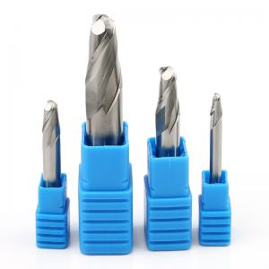
Carbide End Mill R4 Ball Nose HRC45 2F Tungsten Steel Aluminum
Milling Cutter 45 Degree
Characteristic:
- Compared with the end milling cutter, the ball cutter does not have
a sharp blade at the bottom of the end milling cutter, but a blade
with an R angle, so the blade of the ball cutter is stronger and
not easy to break
- The contact area between the ball cutter and the workpiece is the
blade with an R angle, so a larger value can be used for tool
spacing during finishing
- Ball cutters are most commonly used to mill 3D molds in mold
processing, but they are not suitable for milling flat areas.
Because of the small contact area with the workpiece, the tool
spacing cannot be increased
Description:
- A more stable processing state can be obtained: when using the ball
nose carbide end mill for processing, the cut in angle changes
continuously without sudden change, so the change of cutting force
is a continuous change process, which can ensure a more stable
cutting state and a higher surface finish.
- Ball head carbide end mill is used for semi finishing and finishing
of curved surfaces: the spindle motor we use has a poor ability to
resist axial force, so it is generally not allowed to use ball head
cutter for rough machining, while in semi finishing, it is very
good to use ball head cutter. After semi finishing with a ball end
cutter, there is less machining residue, which is more conducive to
the following finishing. The path spacing of semi finishing is
generally the two sides of the finishing spacing. If the method of
parallel intercept is used, it is 90 degrees from the tool path
direction of finishing.
- Reduced the actual cutting radius: just like the use of a bull nose
knife, the use of a ball nose carbide end mill reduces the actual
cutting diameter, reduces the cutting linear speed, reduces the
cutting power and cutting torque during cutting, and is more
conducive to the processing of the spindle motor in a better state.
Milling parameters:
HRC45 Carbide End Mill
| Tool length | fz&v |
| Short | 1 |
| Long1 | 0.9 |
| Overlength | 0.8 |
| Speciality | 0.6 |
| Type | Material | Strength N/mm²
Hardness HRC | Cooling |
| Air | Dry cutting | Lubricating fluid |
| P | PI | P1.1 | Non alloy structural steel, free cutting structural steel,
carburized steel and quenched and tempered steel | <700 | √ | √ | √ |
| P1.2 | quenched and tempered steel | <1200 | √ | √ | √ |
| P2 | P2.1 | Alloyed nitrided steel, carburized steel and quenched and tempered
steel | <900 | √ | √ | √ |
| P2.2 | Tool steel, bearing steel, spring steel and high-speed steel | <1400 | √ | | √ |
| P3 | P3.1 | Tool steel, bearing steel, spring steel and high-speed steel | <900 | √ | √ | √ |
| P3.2 | Tool steel, bearing steel, spring steel and high-speed steel | <1500 | √ | | √ |
| Sloting |
Vc
(m/min) | fz(mm/Tooth) |
| Diameter |
| 2 | 4 | 6 | 8 | 10 | 12 | 16 | 20 |
| 112 | 0.01 | 0.018 | 0.026 | 0.034 | 0.041 | 0.048 | 0.06 | 0.069 |
| 92 | 0.01 | 0.017 | 0.025 | 0.032 | 0.038 | 0.045 | 0.056 | 0.065 |
| 100 | 0.01 | 0.018 | 0.026 | 0.034 | 0.041 | 0.048 | 0.06 | 0.069 |
| 72 | 0.009 | 0.015 | 0.022 | 0.028 | 0.034 | 0.04 | 0.05 | 0.058 |
| 64 | 0.01 | 0.018 | 0.025 | 0.032 | 0.039 | 0.045 | 0.057 | 0.066 |
| 56 | 0.009 | 0.016 | 0.023 | 0.029 | 0.036 | 0.041 | 0.052 | 0.06 |
| Roughing |
Vc
(m/min) | fz(mm/Tooth) |
| Diameter |
| 2 | 4 | 6 | 8 | 10 | 12 | 16 | 20 |
| 228 | 0.018 | 0.031 | 0.045 | 0.057 | 0.070 | 0.081 | 0.101 | 0.118 |
| 208 | 0.017 | 0.029 | 0.042 | 0.054 | 0.065 | 0.071 | 0.095 | 0.11 |
| 184 | 0.018 | 0.031 | 0.045 | 0.057 | 0.070 | 0.081 | 0.101 | 0.118 |
| 144 | 0.015 | 0.026 | 0.037 | 0.048 | 0.058 | 0.068 | 0.085 | 0.098 |
| 132 | 0.017 | 0.03 | 0.042 | 0.054 | 0.066 | 0.077 | 0.096 | 0.112 |
| 112 | 0.015 | 0.027 | 0.039 | 0.05 | 0.060 | 0.07 | 0.088 | 0.102 |
| Finish |
Vc
m/min | fz(mm/Tooth) |
| Diameter |
| 2 | 4 | 6 | 8 | 10 | 12 | 14 | 16 | 18 | 20 |
| 332 | 0.028 | 0.05 | 0.07 | 0.091 | 0.11 | 0.128 | 0.144 | 0.16 | 0.173 | 0.186 |
| 272 | 0.026 | 0.046 | 0.066 | 0.085 | 0.103 | 0.12 | 0.135 | 0.15 | 0.162 | 0.173 |
| 304 | 0.028 | 0.05 | 0.07 | 0.091 | 0.11 | 0.128 | 0.144 | 0.16 | 0.173 | 0.186 |
| 212 | 0.023 | 0.041 | 0.059 | 0.076 | 0.092 | 0.107 | 0.121 | 0.134 | 0.145 | 0.155 |
| 196 | 0.027 | 0.047 | 0.067 | 0.086 | 0.104 | 0.122 | 0.137 | 0.152 | 0.165 | 0.177 |
| 168 | 0.024 | 0.043 | 0.061 | 0.079 | 0.095 | 0.111 | 0.125 | 0.139 | 0.150 | 0.161 |
Note:
- If the following carbide end mill cannot meet your requirements, we
support OEM customized production. The diameter of 0.2mm to 25mm,
the total length of 50mm to 200mm, 4F, 5F, 6F, 8F and logo can be
customized, including inch size end milling cutter. Please contact
us to select or customize non-standard carbide end mill according
to your needs.
| Specification | Flute Dia(φ) | Flute Length (C) | Shank Dia(D) | Overall Length(L) |
| R0.5*2*d4*50L | 0.5 | 2 | 4 | 50 |
| R0.75*3*d4*50L | 0.75 | 3 | 4 | 50 |
| R1*4*d4*50L | 1 | 4 | 4 | 50 |
| R1.25*5*d4*50L | 1.25 | 5 | 4 | 50 |
| R1.5*6*d4*50L | 1.5 | 6 | 4 | 50 |
| R1.75*7*d4*50L | 1.75 | 7 | 4 | 50 |
| R2*8*d4*50L | 2 | 8 | 4 | 50 |
| R2.5*10*d5*50L | 2.5 | 10 | 5 | 50 |
| R3*12*d6*50L | 3 | 12 | 6 | 50 |
| R4*16*d8*60L | 4 | 16 | 8 | 60 |
| R5*20*d10*75L | 5 | 20 | 10 | 75 |
| R6*24*d12*100L | 6 | 24 | 12 | 100 |
| R7*28*d14*150L | 7 | 28 | 14 | 150 |
| R8*32*d16*100L | 8 | 32 | 16 | 100 |
| R9*36*d18*100L | 9 | 36 | 18 | 100 |
| R10*40*d20*100L | 10 | 40 | 20 | 100 |
- Minimize the use of tool tips to process workpieces: at the
position of the ball head tool tip, the processing linear speed is
0 during actual processing, that is, the tool is not actually
cutting, but grinding. In actual processing, the coolant can not be
added to the cutting area at all, which further leads to greater
cutting heat ratio and reduced tool life.
- For straight wall processing, use contour contour processing
method: try to reduce the phenomenon of ball end cutter processing
downward along the straight wall. Relatively speaking, it is a very
good method to process upward along the straight wall, but it is
difficult to separate them in actual processing. Let's compare the
differences between the two.
- Machining straight wall with contour can reduce downward machining.
If you can use "cutting from bottom to top", this phenomenon can be
avoided. When using "cutting from bottom to top", first consider
whether the cutting capacity of the cutter is too large. If there
are relatively large residues left at the root of the curved
surface after machining above, the cutting capacity of the cutter
may be too large. This will not protect the tool but destroy it.
- The ball end milling cutter shall pay attention to the processing
of deep grooves: when processing deep grooves, the cutter may sink.
Because the chip holding groove of the ball end milling cutter is
relatively small, it is easy to break the cutter when processing
sticky materials (such as red copper) and the feed speed is fast.
Therefore, pay attention to chip removal when using ball end cutter
for machining.
Applications:
Pre-hardened Steel, stainless steel, Die steel, steel plate,
Heat-resistant steel,pipe, copper and aluminum, cast iron,
Nonferrous Metal, Wood, Plastic,FRP and sO on. General-purpose
operation slotting, rilling, profiling.
Q1. The tool breaks when cutting in or pulling out the workpiece
The feed rate and cutting depth can be reduced, and the cutting
edge length can be shortened to the minimum of the necessary
length.
Q2. Tool breaks during normal machining
Reduce the feed rate and cutting depth.
The tool shall be passivated.
Replace the clamp or spring collet.
The tool with high cutting edge number changes the tool with low
cutting edge number to improve chip removal and prevent chip
blockage.
Replace dry milling with wet milling (using cutting fluid), and use
it with vortex tube gun to reduce tool temperature and avoid tool
overheating.
If the wet milling fluid supply direction is changed from the front
to the oblique rear or transverse top, the coolant flow should be
sufficient.
Q3. The tool breaks when the feed direction changes
(1) Use arc interpolation (NC machine tool), or temporarily stop
(temporarily) feeding.
(2) Reduce (decrease) the feed before and after the direction
change.
(3) Replace the clamp or spring collet.
Q4. Problem: Part of the blade tip breaks
Chamfer the corners with manual grinding.
Change down milling to up milling.
Company Profile
Introduction Of BWIN
SHENZHEN BWIN PRECISION TOOLS(SHENZHEN)CO.,LTD.(hereinafter referred to as BWIN company) is
located in Songgang Industrial Zone-Shenzhen City-the largest
tungsten carbide products manufacture center in Asia.
BWIN company has advanced production technology, a strong
scientific research and development team, modern standard indexable
insert production line, CNC turning tool bar production line,
overall Carbide end mill production line, PVD coating production
line, and established a research and development center integrating
scientific research and application research.
BWIN company specializes in providing customers with various
marking and non-standard PVD and CVD coatings,high-precision
turning, milling, parting, drilling, grooving and indexable thread
maching CNC Inserts and cutting tools. and with a variety of
processing of materials suitable for finishing,semi-finishing and
roughing the corresponding chip-breaking groove. dedicated to
providing technical solution for auto parts , machine tools,
moulds. aerospace and other industries. The company strives to
produce various kinds of cutting tools to meet customer's
challenging damands.
BWIN company always adheres to customer-centered and
customer-oriented, vigorously promotes technological innovation,
vigorously promotes technological innovation, fully implements the
quality management system and environmental management system,
closely focuses on customer needs, and continuously improves
product quality and technical services.
BWIN Company adheres to the principle of "integrity and innovation, mutual benefit and win-win" to create higher value for customers is our constant commitment,
BWIN Company sincerely looks forward to cooperating with you!