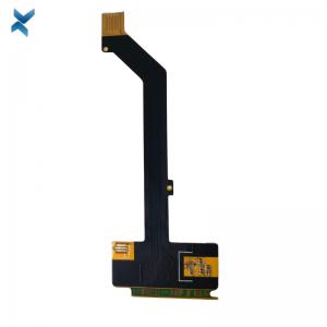
Gold Flashed Rigid Flex PCB Board 2 layers For Imaging Equipment
Brand Name:YScircuit
Certification:ISO9001,UL,REACH, RoHS
Model Number:YS-RF-31
Minimum Order Quantity:1
Delivery Time:2-8 work days
Payment Terms:T/T,PayPal, Alibaba pay
Contact Now
Add to Cart
Verified Supplier
Location:
Shenzhen China
Address:
Shenzhen YingSheng Technology Co., Ltd 805, Tongxin Technology Building, Qiaotou Community, Fuhai Street, Baoan District, Shenzhen
Supplier`s last login times:
within 34 hours
Shipping
lt's easy to get a shipping quote! Just click the button below and complete the short form.
Get Shipping Quote
Product Details
Company Profile
Product Details
Gold Flashed Rigid Flex PCB Board 2 layers For Imaging Equipment
Rigid Flex PCB Gold Flashed Printed Circuit Boards For Imaging Equipment
What is a Rigid-Flex PCB?
A Rigid-Flex PCB is a hybrid circuit board combining elements of
both flexible circuit boards and rigid circuit boards, with an end
result of a board that is able to be folded or continuously flexed
and is normally formed into a flexed shape or curve during the
manufacturing process.
The flexible layers of a Rigid-Flex PCB are buried within the board and penetrate through the rigid sections of the PCB.
Rigid-Flex design
The designs of Rigid-Flex PCBs are a little more complex as these
boards are designed in 3D, which allows the board to be folded or
twisted to create the desired shape for the product. Designing a
board in 3D means they can offer greater spatial efficiency and can
subsequently be used in special instances where space and weight
reduction may be necessary, such as in medical devices.
Rigid-Flex PCBs are usually thinner than other boards, meaning it’s a great option for any thin or light packaging needs your products may have. With thin copper layers and adhesive-less laminates, it’s a great small, thin and light solution for your circuit design needs.
Flex to install & dynamic flex PCBs
There are two common types of Rigid-Flex PCBs; flex to install and
dynamic flex.
Flex to install: this is the most common of the two and applies when a board only folds once, either when the device or product is assembled or dismantled, but is otherwise sturdy and stable throughout.
Dynamic flex: a dynamic flex board will be used when a product is required to fold and bend when in use, meaning they are highly durable and can last through a thousand flex cycles.
Whilst the design might be a touch more complex, and the process slightly more time consuming than the usual printed circuit board, they are an investment worth making with their versatile and durable nature.
Rigid-Flex benefits
There are several benefits to a Rigid-Flex PCB which could make it
a perfect choice for your product, including:
Reduced space requirement through 3D ability.
Shock resistance: Rigid-Flex PCBs can withstand high-stress
environments.
Increased reliability: due to the reduced need for solder joints or connectors, Rigid-Flex PCBs are a brilliant choice for products where a connector or cable failure could be detrimental.
Rigid-Flex PCBs also have a simpler assembly process as they have fewer cables and connectors being used throughout.
If your product requires a board that needs to be folded when assembled or you’re after something highly durable and long-lasting then a Rigid-Flex PCB might be the right fit for you.
| YScircuit Rigid Flex PCB manufacturing capabilities overview |
| Feature | capabilities | |
| Layer Count | 2-20L | |
| Rigid-Flex Thickness | 0.3mm-5.0mm | |
| PCB thickness in flex section | 0.08-0.8mm | |
| copper Thickness | 1/4OZ-10OZ | |
| Minimum line Width and Space | 0.05mm/0.05mm(2mil/2mil) | |
| Stiffeners | Stainless steel,PI, FR4 etc. | |
| Material | Polyimide Flex+FR4,RA copper, HTE copper, polyimide, adhesive,Bondply | |
| Min mechanical Drilled Size | 0.15mm(6mil) | |
| Min laser Holes Size: | 0.075mm(3mil) | |
| Surface Finish | Suitable Microwave/RF PCB urface finishes: Electroless Nickel, Immersion Gold, ENEPIG, Lead free HASL,Immersion Silver.etc. | |
| Solder Mask | Green, Red, Yellow, Blue, White, Black, Purple, Matte Black, Matte green.etc. | |
| Covrelay (Flex Part) | Yellow Coverlay, WhiteCoverlay,Black Coverlay | |
| layer/m² | S<1㎡ | S<3㎡ | S<6㎡ | S<10㎡ | S<13㎡ | S<16㎡ | S<20㎡ | S<30㎡ | S<40㎡ | S<50㎡ | S<65㎡ | S<85㎡ | S<100㎡ |
| 1L | 4wds | 6wds | 7wds | 7wds | 9wds | 9wds | 10wds | 10wds | 10wds | 12wds | 14wds | 15wds | 16wds |
| 2L | 4wds | 6wds | 9wds | 9wds | 11wds | 12wds | 13wds | 13wds | 15wds | 15wds | 15wds | 15wds | 18wds |
| 4L | 6wds | 8wds | 12wds | 12wds | 14wds | 14wds | 14wds | 14wds | 15wds | 20wds | 25wds | 25wds | 28wds |
| 6L | 7wds | 9wds | 13wds | 13wds | 17wds | 18wds | 20wds | 22wds | 24wds | 25wds | 26wds | 28wds | 30wds |
| 8L | 9wds | 12wds | 15wds | 18wds | 20wds | 20wds | 22wds | 24wds | 26wds | 27wds | 28wds | 30wds | 30wds |
| 10L | 10wds | 13wds | 17wds | 18wds | 20wds | 20wds | 22wds | 24wds | 26wds | 27wds | 28wds | 30wds | 30wds |
| 12L | 10wds | 15wds | 17wds | 18wds | 20wds | 20wds | 22wds | 24wds | 26wds | 27wds | 28wds | 30wds | 30wds |
| 14L | 10wds | 16wds | 17wds | 18wds | 20wds | 20wds | 22wds | 24wds | 26wds | 27wds | 28wds | 30wds | 30wds |
| 16L | 10wds | 16wds | 17wds | 18wds | 20wds | 20wds | 22wds | 24wds | 26wds | 27wds | 28wds | 30wds | 30wds |
FQA
Q: If I need the same PCBs in the future do I need to resend the
data?
A: No, you don’t. We safely and securely retain your PCB
information on record. This includes various revisions.
Q: How do you test the PCBs?
A: We use a state of the art flying probe tester, more than 3
square meter use E-testing.
Q: How should PCBs be stored to maximise shelf life?
A: PCBs should be vacuum sealed and stored in a dark dry location
at room temperature.
Q: Can you do complex curved outlines on your printed circuit
boards?
A: The substrate itself is coloured by pigment in the epoxy resin,
which is used together with glass-fibre reinforcement to make up
the finished board, which sits beneath the copper tracks.
Our standard range of PCB colours is available for immediate
manufacture, however, if you have a requirement for a specific
colour, please contact us.
Q: Can I have my printed circuit boards left in a panel for
assembly?
A: The substrate itself is coloured by pigment in the epoxy resin,
which is used together with glass-fibre reinforcement to make up
the finished board, which sits beneath the copper tracks. Our
standard range of PCB colours is available for immediate
manufacture, however, if you have a requirement for a specific
colour, please contact us.


Gold Flashed Rigid Flex PCB Board 2 layers For Imaging Equipment
Inquiry Cart
0