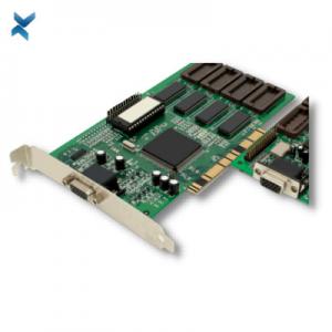
0.8 Oz Copper PCB Quick Turn FR4 Material For Welding Equipment
Brand Name:YScircuit
Certification:ISO9001,UL,REACH, RoHS
Model Number:YS-QT-0012
Minimum Order Quantity:1 piece
Delivery Time:2-8 days
Payment Terms:T/T,PayPal, Alibaba pay
Contact Now
Add to Cart
Verified Supplier
Location:
Shenzhen China
Address:
Shenzhen YingSheng Technology Co., Ltd 805, Tongxin Technology Building, Qiaotou Community, Fuhai Street, Baoan District, Shenzhen
Supplier`s last login times:
within 34 hours
Shipping
lt's easy to get a shipping quote! Just click the button below and complete the short form.
Get Shipping Quote
Product Details
Company Profile
Product Details
Quick Turn PCBA Large Side Customization PCB Assembly For Welding Equipment
To detail other features and benefits available with quick turn, the following outline is provided:
Quick turn PCBs help save time taken by manufacturers for an otherwise end-to-end assembly process.
Most quick turn PCB assemblies are built using flex PCBs, which can be made bendable, compact, and can also be heat and vibration resistant, among other physical parameters.
The size of the quick turn PCB meets the growing demand for small-sized communication devices, and it is applicable in the IoT area.
Quick turn encourages prototyping, increases the speed of prototype production and even research and development, thereby enabling manufacturers to improve their time-to-market potential.
Prototypes help detect and fix possible errors in the early stages. It also creates opportunities to add more features and improve performance.
Quick turn PCBs help manufacturers fulfill the time-related commitment made to the customer while minimizing the overall costs.
Quick turn flex PCBs have high tensile strength, improved heat dissipation, durability, and the ability to enhance airflow.
Once they have been manufactured, quick turn PCBs can be assembled within 24 hours.
Prototyping is an essential efficient and cost-saving strategy employed in quick turn PCB manufacturing, to ensure short turn times and delivery times.
The turnaround time for a quick turn rigid PCB is as low as 24 hours, while flex and rigid-flex PCBs may require about 7 days turnaround time. This is due to board and design complexities.
| layer/m² | S<1㎡ | S<3㎡ | S<6㎡ | S<10㎡ | S<13㎡ | S<16㎡ | S<20㎡ | S<30㎡ | S<40㎡ | S<50㎡ | S<65㎡ | S<85㎡ | S<100㎡ |
| 1L | 4wds | 6wds | 7wds | 7wds | 9wds | 9wds | 10wds | 10wds | 10wds | 12wds | 14wds | 15wds | 16wds |
| 2L | 4wds | 6wds | 9wds | 9wds | 11wds | 12wds | 13wds | 13wds | 15wds | 15wds | 15wds | 15wds | 18wds |
| 4L | 6wds | 8wds | 12wds | 12wds | 14wds | 14wds | 14wds | 14wds | 15wds | 20wds | 25wds | 25wds | 28wds |
| 6L | 7wds | 9wds | 13wds | 13wds | 17wds | 18wds | 20wds | 22wds | 24wds | 25wds | 26wds | 28wds | 30wds |
| 8L | 9wds | 12wds | 15wds | 18wds | 20wds | 20wds | 22wds | 24wds | 26wds | 27wds | 28wds | 30wds | 30wds |
| 10L | 10wds | 13wds | 17wds | 18wds | 20wds | 20wds | 22wds | 24wds | 26wds | 27wds | 28wds | 30wds | 30wds |
| 12L | 10wds | 15wds | 17wds | 18wds | 20wds | 20wds | 22wds | 24wds | 26wds | 27wds | 28wds | 30wds | 30wds |
| 14L | 10wds | 16wds | 17wds | 18wds | 20wds | 20wds | 22wds | 24wds | 26wds | 27wds | 28wds | 30wds | 30wds |
| 16L | 10wds | 16wds | 17wds | 18wds | 20wds | 20wds | 22wds | 24wds | 26wds | 27wds | 28wds | 30wds | 30wds |
| 0-0.5m2 | 0.5-1m2 | 1-3m2 | 3-5m2 | 5-10m2 | |
| 1-2L | 24H | 24H | 3wds | 4wds | 5wds |
| 4L | 24H | 48H | 4wds | 5wds | 6wds |
| 6L | 48H | 48H | 4wds | 6wds | 6wds |
| 8L | 48H | 36H | 5wds | 6wds | 8wds |
| Technical index | Mass Batch | Small batch | Sample | ||
| Base Material | FR4 | Normal Tg | Shengyi S1141,KB6160(not suitable for lead free process) | ||
| Middle Tg | For HDI, multi layers: SY S1000H,ITEQIT158.TU-662 | ||||
| High Tg | For thick copper, high layer: SY S1000-2;ITEQIT180A;ISOLA:FR408R;370HR;TU-752; | ||||
| Halogen Free | Middle Tg:SYS1150G.H160HF;high Tg: SYS1165 | ||||
| High CTI | CTl≥600 SY S1600 | ||||
| High Frequency | Rogers,Arion,Taconic,SY SCGA-500.S7136 | ||||
| High Speed | SYS7439,TU-862HF.TU-872SLK;ISOLA:l-Speed.1-Tera@MT40; | ||||
| Flex Materia | Base | Glue-free:Dupont AK XingyangW-type,Panosonic RF-775; | |||
| Coverlay | SY SF305C.Xingyang O-type | ||||
| Special PP | No flow PP:VT-447LF.Taiguang 370BL Arion 49N | ||||
| Ceramic filled adhesive sheetRogers4450F | |||||
| PTFE adhesive sheetArion6700.Taconic FR-27/FR-28 | |||||
| Double-sided coating PExingyang N-1010TF-mb | |||||
| Metal Base | Berguist Al-base, chaosun Al-base,copperbase | ||||
| Special | High heat resistance rigidity Pl: TenghuiVT-901.Arion85N.SY S260(Tg250) | ||||
| High thermal conductivty material: 92ML | |||||
| Pure ceramic matenal: alumna ceramic.Aluminum nitride ceramics | |||||
| BT material: Taiwan Nanya NGP-200WT | |||||
| Layers | FR4 | 20 | 36 | 48 | |
| Rigid8Flex/(Flex) | 16(6) | 16(6) | 24(6) | ||
| High Frequency Mixed Lamination | 12 | 12 | 20 | ||
| 100% PTFE | 6 | 6 | 10 | ||
| HDI | 4 steps | 4 steps | 4 steps | ||
| Technical lndex | Mass Batch | Small Batch | Sample | ||
| Delivery Size | Max(mm) | 1200*560 | 1200*560 | 1200*560 | |
| (mm) | Min(mm) | 20*20 | 10"10 | 5*10 | |
| Finish board thickness | Max(mm) | 10 | |||
| Min(mm) | 0.3 | ||||
| Width/Gap | Inner(mil) | 0.5OZ base cooper: 3/3 1.0OZ base copper: 4/42.0OZ base copoer: 516 | |||
| 3.0OZ base cooper: 7/9 4.0OZ base copper: 8/12 5.0OZ base copper: 10/15 | |||||
| 6.0OZ basecooper: 12/18 10OZ basecopper: 18/24 12OZ base copper: 20/28 | |||||
| Outer (mil) | 1/3OZ base copper: 3/3 0.5OZ base copper: 4/4 1.0OZ base copper: 5/5 | ||||
| 2.0OZ base cooper: 6/8 3.0OZ base copper: 7/10 4.0OZ base copper: 8/13 | |||||
| 5.0OZ base cooper: 10/16 6.0OZ base copper: 12/18 10OZ base copper:18/24 | |||||
| 12OZ base copper: 20/28150Z base copper: 24/32 | |||||
| Line Width Tolerance | >5.0 mil | ±20% | ±20% | ±1.0mil | |
| ≤5.0 mil | ±1.0mil | ±1.0mil | ±1.0mil | ||
| Drilling | Min laser(mm) | 0.1 | 0.1 | 0.1 | |
| Min CNC(mm) | 0.2 | 0.15 | 0.15 | ||
| Max CNC drill bit (mm) | 6.5 | 6.5 | 6.5 | ||
| Min Half Hole(mm) | 0.5 | 0.4 | 0.4 | ||
| PTH Hole(mm) | Normal | ±0.1 | ±0.075 | ±0.075 | |
| Pressing Hole | ±0.05 | ±0.05 | ±0.05 | ||
| Hole Angle(conical) | Width of upper diameters≤6.5mm:800,900,1000,1100:Width of upper diameters≤65mm:900; | ||||
| Frecision of Depth-control Drilling (mm) | ±0.10 | ±0.075 | ±0.05 | ||
| Number of blind CNC holes of one sidd | ≤2 | ≤3 | ≤4 | ||
| Minimum via hole spacing (different network, military, medical, automobile )mm | 0.5 | 0.45 | 0.4 | ||
| Minimum via spacing(different network, general industrial control and consumer electronic ) mm | 0.4 | 0.35 | 0.3 | ||
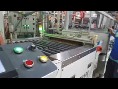
YScircuit Print Circuit Boards Production Process
PCB Stack UP
WHAT IS AN ALUMINUM PCB?
A PCB generally consists of three layers. A conductive copper layer at the top, a dielectric layer in between, and a layer of a substrate at the bottom. Standard PCBs have a substrate layer made of fiberglass, ceramic, polymers, or any other non-metal core. An ample amount of PCBs uses FR-4 as the substrate.
Aluminum PCBs use an Aluminum substrate. Instead of standard FR-4 as the substrate material.
Circuit Copper Layer
This layer transmits signals over the entire PCB board.
The movement of charged particles generates heat.
This heat is transferred to the Aluminum substrate. Which dissipates it efficiently.
Insulating Layer
This layer is also known as the dielectric layer.
It is made of materials that are poor conductors of electricity.
It absorbs the heat generated in the above layer. And transfer it to the Aluminum substrate below it.
Substrate
The substrate acts as a foundation for the PCB.
It firmly holds the components above it. By changing the characteristics of the substrate, the performance of PCB varies.
For example, a rigid substrate provides strength and durability to the PCB board.
While a flexible substrate opens up more design options.
The aluminum substrate is used in power electronics-based applications where high thermal dissipation is required.
Due to its good thermal conductivity, it keeps heat away from vital electronic components. Thus ensuring minimal circuit damage.
ALUMINUM PCBs MANUFACTURED AT YScircuit
YScircuit is one of the finest manufacturers of Aluminum PCBs.
To increase the overall performance of the product, they provide a thermal clad layer to the Aluminum PCB.
It dissipates heat in a highly efficient manner. For high power and tight tolerance based applications Aluminum Backed PCB is the perfect choice among project makers.
Considering parameters like the coefficient of thermal expansion, thermal conductivity, strength, hardness, weight, and cost. Aluminum plate is an ideal choice for your project. You can modify your PCB substrate. PCBWay offers different Aluminum plates like 6061, 5052, 1060, and many more.
ADVANTAGES OF ALUMINUM PCB
1. The heat dissipation capacity of Aluminum PCBs is far better than standard PCBs.
2. Aluminum PCBs provide more strength and durability. As compared to ceramic and fiberglass-based PCBs.
3. It seems ironic, but aluminum-based PCBs are lighter. As compared to standard PCBs.
4. Thermal expansion and contraction of PCB components get reduce by using Aluminum PCB.
5. PCBs made of Aluminum are environmentally friendly. It is non-toxic and recyclable. It does not create any harmful impacts on our planet.
6. The assembling process of Aluminum PCB is easy than that of standard PCB.
APPLICATIONS
1. They are used in Power supply devices like switching regulators, DC/AC converter, SW regulator.
2. In power modules, they are used in inverters, solid-state relays, and rectifier bridges.
3. In automobiles, they are used in an electronic regulator, ignition, power supply controller, etc.
4. They are the perfect choice for amplifiers. Balanced amplifier, audio amplifier, power amplifier, operational amplifier, high-frequency amplifier.
5. They are used in the transmitting and filtering circuit.
6. They are used to make the CPU board. And power supply of computers.
7. Electric motors require a high current for their operation. In industries, motor driver circuits use Aluminum PCB.
8. These are a popular choice for LED applications due to their energy-saving capability.


0.8 Oz Copper PCB Quick Turn FR4 Material For Welding Equipment
Inquiry Cart
0