
Add to Cart
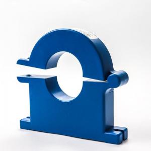
Fast Response Hall Effect Current Sensor Small Size Light Weight
Easy Installation
The Hall sensor is a magnetic field sensor made according to the
Hall effect. Hall effect is a kind of magnetoelectric effect. This
phenomenon was discovered by Hall (A.H.Hall, 1855-1938) in 1879
when he was studying the conductive mechanism of metals. Later, it
was found that semiconductors and conductive fluids also have this
effect, and the Hall effect of semiconductors is much stronger than
that of metals. Various Hall elements made of this phenomenon are
widely used in industrial automation technology, detection
technology and information processing, etc. aspect. The Hall effect
is a basic method for studying the properties of semiconductor
materials. The Hall coefficient measured by the Hall effect
experiment can determine important parameters such as the
conductivity type, carrier concentration, and carrier mobility of
semiconductor materials.
Characteristic
CAB500 Series current sensor is based on Sinomags Active Close Loop
technology,
with CANBUS digital output. It can be used to measure 500A rated
current. Using a proprietary Digital Compensation technology. This
product brings the best combination of performance and reliability.
Error ± 0.2A @ ±<30A, Error ±0.5A @ ±<100A; Error ±1.0A @
±100A-300A; Error ±1.5A @ >±300-500A.
High electromagnetic compatibility against complex electromagnetic interference environment.
Excellent anti magnetic interference.
Can bus output, convenient for system integration.
Ultra-high over current capability
General parameters
Working temperature: -40°C~+85°C;
Insulation resistance: >= 500 MΩ;
Rms voltage for AC insulation test 50Hz 1min 2.5KV Over-voltage
24V/1 minute
Electrostatic discharge voltage 4KV
Installation | Standard rail+Plane screw fixation |
Original side rated current | 50A;100A;200A;500A; 800A;1000A;customization |
Original side measurement range | 100A-1200A |
Rated output | 5V;DC0~20mA;DC4~20mA;customization |
Auxiliary power supply | DC12V,DC24V,DC±12V,DC±15V |
Load capacity | Voltage output:5mA; Current output:6V; |
Linearity | 0.005 |
Accuracy | 0.01 |
Response time | <200ms |
Temperature drift | ≤500PPM/℃ |
Band width | DC~20KHz |
Consumption of current | ≤25mA |
Working temperature | -10℃~+70℃ |
Storage temperature | -25℃~+85℃ |
Isolation pressure resistance | 2.5kV/50Hz,1Min |
Offset voltage | ≤20mvV |
Zero output | ≤0.15mA |
di/dt follow | >50A/uS |
Electrical parameters
Parameter | Symbol | Unit | Specification | Conditions | ||
Min | Type | Max | ||||
Nominal Measuring Range | IPN | A | -500 | 500 | ||
Supply Voltage | UC | V | 7.2 | 12 | 18 | Full accuracy |
Current Consumption @IP=0A | IC | mA | 26 | UC=12V, T=25°C | ||
Current Consumption @IP=500A | IC | mA | 250 | UC=12V, T=25°C | ||
Sensitivity error Accuracy | XG | % | -0.5 | 0.5 | =-40 to 85°C; | |
Offset=0A | IOS | A | ±0.2 | =-40 to 85°C; ± 3 sigma | ||
Linearity error with IPN | εL | % | 0.1 | @room temperature | ||
Temperature coefficient of G | TCG | ppm/ | ||||
CAB-500 CAN Output specification
CANBUS speed refer to product version table, CANBUS protocol:
version 2.0A/B
CAN oscillator tolerance: 0.3125%
Byte order: big endian (Motorola)
120 ohm termination resistor to be added externally, internal CAN
impedance = 2.4Kohm
Message Description | CAN ID | name | Data Length (bytes) | Type of frame | Message launch type | Signal description | Signal Name | Start bit | End bit |
Current Ip (mA) | 0x3C2 | CAB500 | 8 | stand ard | Cyclic message every 10ms | Ip Value: 80000000H= 0mA, 7FFFFFFFH= - 1mA, 80000001H= 1mA | IP_VALUE | 0 | 31 |
b0:Error information (0=Normal ,1=failure) | ERROR_INDICATION | 32 | 32 | ||||||
b7-b1:RxQuality (0-100%) | ERROR_INFORMATION | 33 | 39 | ||||||
Vacant bits (fix to 0) | UNDEFINE | 40 | 47 | ||||||
PCBA Ver | 48 | 55 | |||||||
FIRMWARE Ver | 56 | 63 |