0.47 Uf X2 Safety Capacitor 474K For Power Supply High Insulation Resistance
Brand Name:CG
Certification:VDE,CQC
Model Number:X2-474K-275VAC-E41
Minimum Order Quantity:10000 Pieces
Delivery Time:15-21 work days
Payment Terms:T/T
Contact Now
Add to Cart
Verified Supplier
Location:
Dongguan Guangdong China
Address:
Baisha Sancun Industrial Zone, Humen Town, Dongguan City, Guangdong Province, China
Supplier`s last login times:
within 28 hours
Product Details
Company Profile
Product Details
High Insulation Resistance 0.47uf 474K 275VAC X2 Safety Capacitor
For Power Supply Anti-Electromagnetic Interference
X2 Safety Capacitor.pdf
X2 capacitor function
1. Suppress electromagnetic interference of power supply.
The most common function of the X2 safety capacitor is to suppress
the electromagnetic interference of the power supply. It is
generally placed at the entrance of the neutral wire and the live
wire of the power supply. In the power supply, it is usually used
together with the safety Y capacitor. The x-capacitor is a
capacitor connected across the two wires (L-N) of the power line to
suppress common-mode interference. Y capacitors are capacitors that
are connected between the two lines of the power line and the
ground (L-E, N-E), and generally appear in pairs to suppress
differential film interference. If safety capacitors are not used
in the power supply, EMC problems will occur when the power supply
is certified, so safety capacitors are indispensable.
2. Resistor-capacitance step-down effect.
In addition to suppressing the electromagnetic interference of the
power supply, X2 can also be connected in series in the circuit
with a 100~250VAC power supply and used as a RC step-down
capacitor. The resistance-capacitance step-down circuit is
relatively simple and economical, and is often used in some
low-power circuits, such as LED modules and small home appliance
control.
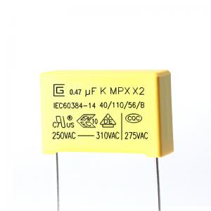
Marking
1. CIGU logo:
2. Capacitance:(104K ,0.1μF)
3. Capacitance Tolerance:(K)±10%
4. Rated Voltage:250,275,300,305,310VAC 5. Product Class:X2
6. Product type: MPX
7. Climatic Category: 40/110/56
8. Passive Flammability Class:B
9. China approvals mark:CQC
10. Germany approvals mark:VDE
11. ENEC approvals mark:ENEC
Products Introduction
MPX are winded with metallized polypropylene film
dielectric,Non-inductive construction, tinned copper wire leads,and
flame retardant epoxy resin coating. They have excellent features
of self-healing and good flame retardant according to UL 94-V0
Features
1 Non-induction construction
2 High moisture-resistance
3 Self-healing property
4 Flame retardant type(compliance with UL 94V-0)
5 Very small loss
Construction and main materials of products
Specifications(IEC 60384-14)
| Test items | Performance requirements | Conditions of test |
| Capacitance | Within the tolerance specified | 1KHz, 1Vrms Max. at 25℃ |
| Dissipation Factor | 0.001 (0.1%) Max. | 1KHz, 1Vrms Max. at 25℃ |
| Voltage proof | Shall be no abnormality | Between terminals 4.3UR (Vdc) Test of 60sec. |
| Between terminal and enclosure UR×200%+1500Vac, 60sec. | ||
| Insulation resistance | CR ≤ 0.33μF IR ≥ 15,000MΩ CR >0.33μF IR ≥6,000s | 100±15Vdc, 60sec / 25℃ |
| Robustness of terminations | No wire breakage and no damage of capacitor | Tense Strength of Terminal Load Force : 1.0 Kg Holding Time : 10 ± 1sec |
Bending Strength of Terminal Load Force : 0.5 Kg Bending Time : 4 x 90 ゚ | ||
| Resistance to soldering heat | (1) Appearance : No visible damage (2) △C/C : ≤ ±5% of the initial value | Solder temperature: 260±5℃ Solder time: 5±0.5sec |
| Solderability | 95% of the surface tinning | Solder temperature: 260±5℃ Solder time: 2±0.5sec |
| Rapid change of temperature | The capacitors shall be visually examined and there shall be no visible damage. | Lower category temperature: -40℃ Upper category temperature: 110℃ Number of cycles: 5 Duration t1 = 30 min |
| Vibration | The capacitors shall be visually examined and there shall be no visible damage | Frequency range: 10~55Hz Course: X,Y,Z (axis) 2h / axis ( 6h in total) Displacement amplitude: 0.75mm |
| Test items | Performance requirements | Conditions of test |
| Climatic sequence | (1) Appearance : No visible damage (2) △C/C : ≤ ±5% of the initial value (3) DF ( tanδ) : ≤ 0.008 of increased value (4) IR : ≥ 50% of the applicable limits (5) Voltage proof : Normal | Dry Heat Upper Temperature: 110℃ Lower Duration: 16Hrs |
Cold Temperature: -40℃ Duration: 2Hrs | ||
| Damp Heat Steady State | (1) Appearance : No visible damage (2) △C/C : ≤ ±5% of the Initial value (3) DF ( tanδ) : ≤ 0.008 of increased value (4) IR : ≥ 50% of the applicable limits (5) Voltage proof : Normal | +40°C and 93% RH, 56 days |
| Charge and discharge | (1) Appearance : No visible damage (2) △C/C : ≤ ±10% of the initial value (3) DF ( tanδ) : ≤ 0.008 of increased value (4) IR : ≥ 50% of the applicable limits | Test voltage : √2 x URVAC 50 Hz Charge and discharge: 0.5sec/time Repeated for 10000 cycles |
| Endurance | (1) Appearance : No Visible Damage (2) △C/C : ≤ ±10% of the initial value (3) DF ( tanδ) : ≤ 0.008 of increased value (4) IR : ≥ 50% of the applicable limits | 1.25 x UR VAC 50 Hz, once every hour increase to 1,000VAC for 0.1 second, 1,000 hours at upper rated temperature |
Storage conditions
1 t should be noted that the solderability of the terminals may be
deteriorted when stored barely in an atmosphere for a long preriods
2 It shouldn't be located in particularly high temperature and high
humidity, it must submit to the following conditions(keeping in the
original package)
Temperature: 35 MAX Relative humidity:60% MAX
3 Storage period:Losse:12 monthes max (from the manufacturing date
marked on the label in package bag)
Enviroment requirement
1 Compliance with the requirement of RoHS.
2 Compliance with the requirement of REACH.
3 Without Halogen(as required).
4 Please see the attachment 2 for the test reprots of the Rohs and
Reach by a third party
Quality Control
Product structure
Packing
Plastic bag is the minimum packing.the quantity are100,200,300,
500,1000PCS.
The label of the RoHS include the product name,specification, quantity, lot No,manufacture date etc.
One inner box have N PCS bags
Inner box size (L×W×H)=23×30×30cm Marking for RoHS AND SVHC
One outer box have two Inner boxes
Outer box size (L×W×H)=48×32.2×33cm Marking for RoHS AND SVHC


0.47 Uf X2 Safety Capacitor 474K For Power Supply High Insulation Resistance
Inquiry Cart
0