
Add to Cart
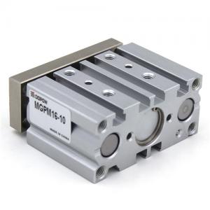
MGP Series Cylinder Compact Guide Rod Pneumatic Actuator
MGPM16-10 Series Replace SMC MGP Compact Guide Cylinder
| Model | Bore size | Port size | Standard stroke mm | Max.theoretical force | Piston port size | Available accessories | Mode | Maxoperating pressure |
| MGPM12 | 12 | M5 | 5〜50 | 10Kgf | M3X0.5,M5X0.8 | D-Z73 | MGP: | 0^10/kgf/cm2 |
| MGPM16 | 16 | M5 | 5〜50 | 14Kgf | M3X0.5,M5X0.8 | |||
| MGPM20 | 20 | M5 | 5〜50 | 28Kgf | M4X0.7.M6X1 | |||
| MGPM25 | 25 | M5 | 5~50 | 44Kgf | M5X0.8.M8X1.25 | |||
| MGPM32 | 32 | PT1/8 | 5-500 | 70Kgf | M6X1.M10X1.25 | |||
| MGPM40 | 40 | PT1/8 | 5 〜500 | 110Kgf | M8X1.25.M14X1.5 | |||
| MGPM50 | 50 | PT1/4 | 5-500 | 170Kgf | M10X1.5.M18X1.5 | |||
| MGPM63 | 63 | PT1/4 | 5-500 | 280Kgf | M10X1.5.M18X1.5 |
A voltage at which the auto switch can be used.
The operating voltage is indicated using generally used voltages
(24 VDC, 100 VAC, etc.).
For the 2-wire type, the operating voltage has the same meaning as
the power supply voltage or load voltage.
Operating current range
A range of the current value that can be flowed to the output of
the auto switch.
If the operating current is lower than this range, the auto switch
may not operate correctly. Conversely, if the operating current is
higher than this range, the auto switch may break.
Current consumption
This current value is necessary for the 3-wire type auto switch to
operate the circuit through the power cable. For the 2-wire type,
as the current consumption is a part of the load current, it is not
defined.
Insulation resistance
A resistance between the electric circuit and enclosure.
Unless otherwise specified, 50 MΩ (Min) is used for auto switches.
Magnetic field resistant auto switch
An auto switch with protection against the effects of external
(welding) magnetic fields generated in the spot welding process,
etc.
The solid state auto switch is able to function as it detects the
frequency of the applied magnetic field. If an external magnetic
field (AC) is applied, the last signal is retained and the product
remains unaffected by the external magnetic field. This system can
be used with cylinders with normal magnetic force.
The reed auto switch features a built-in magnetic field shielded
sensor with low sensitivity that reduces the effects of external
magnetic fields (DC or AC magnetic fields). Therefore, a dedicated
cylinder with a strong built-in magnet needs to be selected, and
the operable range (conditions) need to be considered.
Impact resistance value
A minimum acceleration that may cause the auto switch to
malfunction or break when the standard impact is applied.
Water-resistant auto switch
In contrast with the general (general purpose) product, structural
measures have been taken in order to provide this model with
long-term water resistance.
Withstand voltage
A tolerated dose of voltage that can be applied to the portion
between the electrical circuit and enclosure.
The withstand voltage shows the strength level of the product
against the voltage. If a voltage exceeding the withstand voltage
is applied, it may cause the product to break. (The voltage
described here is different from the power supply voltage necessary
to operate the product.)
Proper mounting position
A dimension that shows the mounting position when the position is
detected at the stroke end of the cylinder.
When this position is set, the maximum sensitivity position is
aligned with the center of the magnet. However, make the nec-
essary adjustments to the actual machine by considering the
characteristic differences of the actual setting.
When an adjustment allowance is needed for the detection before the
stroke, set a value with an adjustment allowance added to the
proper mounting position.
Applicable load
A device that is assumed as a target load of the auto switch.
Operating time
A period of time until the auto switch output becomes stable after
the magnetic force to operate the auto switch has been received.
Operating range
An auto switch operating range in response to the cylinder piston
movement (ON length in response to the stroke). The oper- ating
range is determined by the magnetic force of the magnet (range in
which the magnetic force
