Add to Cart
I. Basic Information
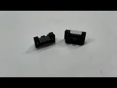
Type: SATA 7P/F (Female, i.e. Female chassis) 90° solder type
(Solder Type) Wire to Board connector.
Number of pins: 7 pins (Pin), in line with the SATA interface standard.
Angle: 90°, this design allows the connector to be mounted at a 90° angle
on the board, which helps to save space and improve layout
flexibility.
II. Product Features
1. Solder Type Connection: Connecting the connector pins to the circuit board by soldering
provides a solid and reliable electrical connection. This type of
connection is especially common in applications requiring high
reliability and durability.
2. Gold-plated contacts: Connector contacts are usually plated with gold (Plated Au) to
improve electrical conductivity, corrosion resistance and wear
resistance, thereby extending the life of the connector.
3.SATA interface standard: Compliant with SATA interface standard, supporting high-speed data
transmission and power connection, ensuring compatibility with
various SATA devices.
4. Compact design: 90° design makes the connector easy to install even in limited
space, suitable for a variety of compact electronic devices.
III. Technical Specifications
Pin Arrangement: According to the standard pin arrangement of SATA 7P, ensuring the
correct mating with the corresponding male connector.
Electrical performance: meets the electrical performance requirements of SATA interface
standards, including voltage withstand, insulation resistance,
contact resistance, etc.
Contacts: made of high quality conductive materials and gold plated to
improve performance.
Insulator: made of materials with good insulation and high temperature
resistance to protect the internal circuit from external
interference.
Fourth, the field of application
The connector is widely used in computers, servers, storage devices
and other fields, especially those devices that require SATA
interface connection and have high requirements for connection
quality. It can be used for connection between motherboards, hard
disk drives, optical drives and other components, providing stable,
high-speed data transmission and power connection.
V. Installation and Precautions
During installation, please make sure that the pins of the
connector correspond correctly to the soldering points on the board
to avoid poor or damaged connections.
Follow the guidelines and recommendations provided by the
manufacturer when soldering to ensure that the soldering quality
meets the requirements.
Regularly check the contact status and electrical performance of
the connector to ensure stable operation of the equipment.