
Add to Cart
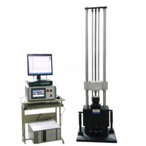
HSKT10 Mechanical Shock Tester
Proposal Description
1 Product application
The shock testing system of HSKT series are mainly applicable to
shock resistance tests in such fields as electronic products,
aerospace, shipping, military industry, automotive parts and
transportation. Shock tests in form of half sine wave, final peak
saw tooth wave or trapezoidal wave shock tests can be carried out
by selecting different waveform generators.
The equipment conforms to such testing specifications as
GB/T2423-2008, GJB150, GJB360, GJB548, GJB1217, MIL-STD-202F,
IEC-68-2-27, MIL-STD-810F, MIL-STD-883E,
Structural schematic diagram of SKT series mechanical shock tester
2 Main performance
1 Free drop type shock tester using hydraulic lifting and HP fluid
braking;
2 Use of pneumatic-hydraulic boosting and strong friction brake to
prevent secondary shock braking;
3 Shock measurement device: single-channel data acquisition,
simultaneous acceleration data measurement, storage, report
printing, data callback, database management of two channels.
4 Use of rubber module, producing a wide range of half sine pulse
with arbitrary action time.
5 Availability for equivalent drop test of packing boxes.
3 Equipment configuration
| configuration No. | Equipment name | Model | Qty. |
| 1 | Shock tester table | HSKT10 | 1set |
| 3 | Controller | SKC-1 | 1 set |
| 4 | Shock measurement device | ST-2 | 1 set |
| 5 | Sensor | LAB | 1pcs |
| 6 | Control computer | 1 set | |
| 7 | Waveform generator | HB01 | 1 set |
| 8 | Safety device | Audible and visual alarm | 1 set |
| 9 | Attached accessories | Tools, clamps/instructions, installation disc, etc. | 1 set |
II Technical Parameters
| Operating platform | 200 × 200 mm |
| Max. load | 10KG |
| Peak acceleration | 20 to 1500G (customization acceptable) |
| Pulse duration | 0.5~11ms (customization acceptable) |
| Equipment dimensions | 560×670×2390mm |
| Equipment weight | 650 kg |
| Power required | 220VAC±10% 50Hz,2kVA |
| Measuring system | |
| Input channels | 2 channels |
| Sampling frequency | 192KHz |
| Pulse duration | 50-1ms |
| Communication interface | USB2.0 |
| Supportive standard | ISO, UN38.3,MIL-STD-810, user defined |
| Operating system | Microsoft Windows7/8 |
| System acceleration sensor | |
| Brand | LAB |
| Model | 23108 |
| Output mode | Charge type |
| Sensitivity | 3.93pC/g |
| Frequency range | 0.5 to 12KHz |
| Acceleration range | ±2500G |
| Operating environment | -40 to +160℃ |
III Introduction to Equipment Performance
1 Operating platform
High-strength imported aluminum alloy operating platform.
3 Lifting height control
The lifting height is measured by a photoelectric encoder module
installed on the base, and the photoelectric encoder module has
high accuracy, strong anti-interference capability and high
reliability, thus ensuring shock repeatability.
4 Braking system
Air brake and strong friction brake are applied to prevent
secondary shock braking, thus ensuring prompt and reliable braking
to prevent secondary bounce.
5 Buffer system
The buffer system is consisted of a base, a damper and a gasbag.
The buffer system can reduce the shock force transferred from the
working platform to the ground.
6 Waveform generator
6.1 Plate-typed half sine wave: for achieving different shock pulse
widths (1 to 30ms)
Trapezoidal wave: special cylinder
7 Safety device
Emergency stop switch: It switches off the circuit in emergency
cases by forcibly disconnecting welded contacts of the actuating
mechanism.
Optional: safety mat
8 Introduction to the shock measuring system and its features
The system conforms to MIL-STD-810, GJB-150-18-86 and IEC68-2-27
standards, and has accurate and prompt shock wave capture
capability. The max. sampling rate is 1MHz, therefore, you need not
worry about omission of minor shock events.
The system is also an integrated solution, you need not be busy
with waveform viewing and recording, as the system can capture
shock event and generate report, more importantly, the system can
provide you with shock response spectrum analysis (SRS) to
facilitate effective assessment of potential damage from shock
pulse to the actual system. At last, the auxiliary analysis on
force deformation and shock response can enable to understand more
details about the shock results.
Features of the measuring system
It conforms to MIL-STD-810, GJB-150-18-86, IEC68-2-27 and DELL
standards.
The max. sampling frequency is up to 1MHz.
The max. testing acceleration is 100000gn.
The min. testing pulse width is 0.1ms.
It has the features of multi-frame waveform recording and playback.
It supports internal and external triggering.
Analysis functions:
Transient capture of shock waveform
You can obtain single or multiple pulses with transient capture.
The system can automatically analyze data of shock pulse, including
peak value, pulse width, rate of speed change and head injury index
(HIC), automatically match the captured pulse waveform to ideal
waveform, and compare their deviation.
Shock response spectrum analysis
The shock response spectrum analysis enables assessment on
potential damage arising from shock, thus providing basis for
designing shock resistance of products. The system can perform SRS
analysis on each shock pulse, and compare the deviation between
actual SRS and objective SRS.
Other analysis
Essential analysis in shock test includes force deformation
analysis, shock response demonstration and rotary shock analysis.
Peak force, deformed peak value, power and energy produced by pulse
are calculated in the force-deformation analysis. Tools for
learning shock response spectrum are provided in the shock response
demonstration. Rotary shock analysis is used for rotary shock
machines or other rotary control events, and the signal can be
obtained by measuring and calculating axial acceleration
V Site requirements
1. Power supply: 220V±10% 50Hz
2. Independent isolated power supply
3. Air supply:0.5--0.8MPa
4. Using environmental conditions:
Temperature Rang::RT℃~35℃;
Humidity range:0--85RH%;
Installation location: flat ground, no corrosive gas surrounded,
less dust.
5. Appropriate unloading, handling tools shall be prepared by
customer.