
Add to Cart
Product introduction:
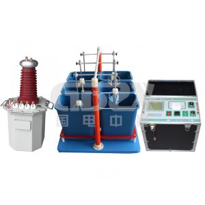
ZXYTM-II Insulated Boots Gloves Pressure Tester is designed and manufactured according to the test procedures of gloves (insulated boots) and complies with the opinions of users. This product effectively solves the irregular test methods in the past, which simplifies the testing procedures and improves the testing speed. More reliable identification of gloves (insulated boots) leakage current, insulation aging, power frequency withstand voltage and other parameters. It is the ideal equipment for gloves (insulated boots).
Its main features: It can test 3 pairs of gloves (insulated boots) at the same time, and can read each leakage circuit to accurately judge the unqualified gloves (insulated boots); the bottom of the structure can be moved freely.
●The insulated boot glove withstand test device effectively solves the past non-standard test.
● It is an ideal equipment for insulated boots (gloves) because it improves work efficiency and ensures work safety
Features:
1. Test with high speed, can improve the efficiency
2. Direct display of voltage and leakage current, auto identify
unqualified products
3. Can test 3 pairs of gloves or boots simultaneously and read out
leakage current for every piece.
4. With trundles at the bottom to make it convenient for moving
Technique Parameter: (Manual type)
| 1. Input voltage: ~220V,50HZ 2. Output voltage:0-30kV or 50kV 3. Capacity:3KVA or 5KVA 4. Measurement quantity: 6 units each time 6. Measurement data: display and print voltage and leakage current for every unit 7. LCD display with print function 8. Accuracy: Voltage±2%(±3 bits)Current ±2%(±3 bits) 9. Total weight about 80-100KG |
Technique Parameter:( Automatic type)
1.Input voltage: 0~220V,50HZ |
Fully automatic insulated boots (gloves) pressure test device instructions:
1. Fill the sink with water (the whole two-thirds of the sink), and fill the test object with water. The insulated boots (gloves) have the same height inside and outside the water. They should have a 90mm exposed surface and ensure that the insulated boots (gloves) are exposed to the water. Dry and clean, then place the high voltage electrode in the insulated boot (gloves) and clip the insulated boots (gloves).
2. Insulated boots (gloves) The grounding end of the test vehicle
is connected to the grounding grid. The grounding end of the
insulating boot (glove) operating box panel is also connected to
the grounding grid and is grounded at the same joint location as
the grounding end of the test vehicle.
3. Check if the total power supply is consistent with the input
power supply (0~220V 50Hz), and connect the operation box to the
test bench with the multi-core cable provided in the operation box.
4. Close the power switch and enter the measurement state. The
system self-tests for a few seconds.
5. Press the test button, please pay attention to the prompt at the
bottom of the display. The high voltage voltage bar on the display
should have a high voltage display (kV) and a leakage current value
(mA) of 6 channels.
6. During the boosting process, the alarm buzzer will sound,
indicating that it is boosting at this time. Please pay close
attention to the voltage and current values. When the voltage rises to the set voltage value, the boost will
stop, and it will automatically time, and will automatically step
down after the time.
7. Pay attention to the leakage current value. If the insulation
performance of the insulated boots (gloves) is reduced, the leakage
current will be indicated. If any current indication exceeds the
range specified by the test product during the test, the system
will automatically cut off the high-voltage power supply, turn off
the power switch to find out the relevant cause and then test.
8. During the boost or withstand voltage test, if an overcurrent
such as short circuit, flashover, or breakdown occurs, the
corresponding data will be displayed in reverse and will be
maintained. The system will automatically return to zero for the
next test.
9. After each test, you must turn off the power switch, then turn on the power switch
to test.