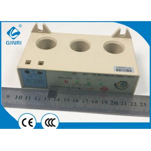
Fans current limiting relay , 40A Phase Failure Protection Relay Integrative Structure
Brand Name:GINRI
Certification:CE CCC
Model Number:JDB-1
Minimum Order Quantity:20Pcs
Delivery Time:1-30 days upon order quantity
Payment Terms:L/C, T/T, Western Union,Paypal
Contact Now
Add to Cart
Active Member
Address:
No.337,Kaichuang Road,Baitawang Industrial Distrit, Beibaixiang Town,Yueqing City,Zhejiang Province,China
Supplier`s last login times:
within 47 hours
Product Details
Company Profile
Product Details
Fans current limiting relay , 40A Phase Failure Protection Relay
Integrative Structure
♦ Features
-- Integrative structure
-- Three-phase monitoring of overload, phase loss, phase unbalance
-- Powered by the measuring circuit
-- 1 NC SCR output contact
-- 4 LEDs for status indication
♦ Protective Functions
-- Overload
-- Phase loss
-- Phase unbalance
♦ Typical Applications
• Pumps • Fans
• Blowers • Motors
• Compressors
♦ Approvals
• CE • CCC
Normal operating conditions and installation conditions
1 , the ambient temperature: -10 °C ~ +50 °C.
2 , relative humidity: ≤ 90%.
3 , atmospheric pressure: 80Kpa ~ 110Kpa.
4 , altitude: not more than 2000 meters.
5 , the grid frequency: 45 ~ 60Hz.
6 , working voltage: 24 ~ 380VAC.
7 , the output interface load capacity: 1A/380VAC.
8 , installation size: in line with JR16 thermal relay standards.
9 , installation location: Any type of installation of type II.
10 . Surrounding environment: Equipment that is resistant to
sunlight, rain, snow, wind, sand;
There is a medium with explosion hazard. The air does not contain
gases that cause metal corrosion, insulation damage, and
conduction.
Medium; No more severe molds and strong vibrations and shocks are
allowed.
Instructions for use and safety precautions
1 . According to the graphical operation, the AC contactor to the
three-phase power line of the motor passes through the three
perforations of the protector, and the phase sequence is arbitrary.
The terminal of the protector is connected in series to the
secondary circuit of the AC contactor. .
2 . First, turn the current regulator knob of the protector
clockwise to the position of the maximum scale value. After
checking the wiring is correct, start the motor and make it in
normal operation. At the same time, the three-phase green luminous
tube of the protector is on. The overload red indicator light is
not Light, then turn the current adjustment knob slowly
counter-clockwise until the overload indicator lights up. At this
time, the protector is in the critical state of overload
protection. Slowly turn back clockwise until the overload indicator
just goes out, then the protector's The scale value of the current
adjustment knob is the current value of the motor overload
protection.
♦ Technical data
| Type | JDB-1 |
| Current range | 2.5-5A,4-10A,8-20A,16-40A,32-80A, |
| Startup delay | 5s,10s,20s |
| Protective functions | overload,phase loss,phase unbalance |
| Setting method | by knob |
| Indicators | ABC overload&phase loss |
| Output contacts | 1NC(SCR output) |
| Contact capacity | 1A 380VAC |
| Operating voltage of control loop | AC220V or AC380V |
| Dimensions(H*W*D) | 2.5-40A:38*90*63mm |
| Mounting | screw fixing |


Fans current limiting relay , 40A Phase Failure Protection Relay Integrative Structure
Inquiry Cart
0