JY02A is a pure hardware application IC, which solve the trouble of
writing programs. JY02A internally solidifies various sensorless
brushless DC motor drive control circuits, such as adaptive start
circuit, power compensation circuit,Q value correction circuit,
power
factor correction, Phase detection circuit, bidirectional operation
decoding circuit,locked-rotor protection circuit, back
electromotive
force detection circuit, current detection & control circuit,
voltage detection & protection circuit, etc., after a very few
amount of
external component adjustment, can drive various sensorless brushless DC motor, JY02A has a certain load-starting
capability,
which is very important in most applications.JY02A can be applied
to three-phase DC brushless motor with "Y" and "triangle"
connection.
Applications:
sweeping robots, automotive water pumps, wall-hung boiler
circulation pumps, home booster pumps,oxygen generators, various
fans/blowers, electric screwdrivers, electric curtains, automatic
doors, hydraulic oil pumps,high pressure air pumps, automotive
air conditioning compressors , DC brushless compressor, AGV
trolley, various linear and loop logistics sorting equipment, lawn
mower, sprayer, underwater propeller, etc.
Functional characteristics:
☆Working voltage: 4.5 v-5.5 V. ☆Working temperature: -55-125 ℃
☆Drive mode: SPWM ☆Adaptive motor: Sensorless BLDC motor
☆Direction control: CW/CCW ☆Soft reversing: Yes
☆Speed signal: Yes ☆Overload protection: Yes
☆Current closed loop: Yes ☆Constant current drive: Yes
☆Blocking protection: Yes ☆Starting torque regulation: Yes
☆Soft starting: Yes ☆Special technology: JYKJ full condition safety
start function
☆Speed adjustment: linear ☆EAI self-adaptation function
Packaging size:
Diagram ofpin function description
DC Electrical Characteristics
JY02A internal functional block diagram
Note: JY02A drive signal is positive polarity output, choosing
adapted MOS drive circuit and power MOS is very important!
JY02A Drive mode and parameters:
1.UH/VH/WH phase top drive PWM output,UL/VL/WL phase bottom drive
commutation signal output, this drive mode is a economic
way to reduce the costs of hardware, especially in application of
high voltage and high-power motor drivers. top drive PWM output
mode is more easier circuit and higher stability than bottom drive
PWM output mode.
2. The PWM frequency of JY02A is 13KHz, which not only takes into
account the comprehensive ratio of efficiency and noise, but also
increases the power and reduces the power consumption of the
driving circuit . The torque of the motor is higher than that of
20KHz
under the same power supply.
Pulse of JY02A
Please take a note that JY02A output one pulse signal during the
BLDC motor commutating phase each time. It means JY02A not
produce one pulse when the motor turn a round. For example as
following schematic diagram: its an inner rotor, 2 pairs pole
motor,
it means the motor needs commutating phase for 6 times for each
round, so JY02A will output 6 pulses each motor round.
Schematic diagram of internal structure of 2 pair pole inner rotor
motor
Forward drive output oscillogram
(SPWM output close to sinusoid, well electromagnetic noise
restraint )
Reversing drive output oscillogram
(SPWM output close to sinusoid, well electromagnetic noise
restraint )
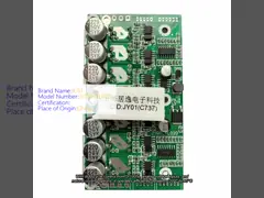
DOWNLOAD THE DATASHEET OF JY02A
JY02A_V2-English2.pdf