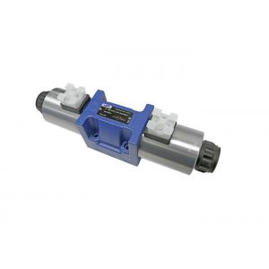
Directional Solenoid Hydraulic Control Valve With Wet Pin AC Or DC WE 10 L5X
Brand Name:Hengli
Model Number:Type WE 10...L5X
Minimum Order Quantity:1 set
Delivery Time:5-30 days upon order quantity
Payment Terms:T/T, Western Union, MoneyGram
Place of Origin:China
Contact Now
Add to Cart
Verified Supplier
Location:
Suzhou Jiangsu China
Address:
No.116.Chengyang Road, Xiangcheng district , Suzhou , China.
Supplier`s last login times:
within 37 hours
Shipping
lt's easy to get a shipping quote! Just click the button below and complete the short form.
Get Shipping Quote
Product Details
Company Profile
Product Details
4/3, 4/2 and 3/2 directional valve with wet-pin AC or DC solenoid
Type WE 10...L5X
Features:
– Direct operated directional spool valve with solenoid operation
– Porting pattern according to DIN 24 340 Form A, ISO 4401, and
CETOP-RP121H
– Wet-pin DC solenoids with detachable coil(AC voltages possible
via a rectifier)
– Solenoid coil can be rotated through 90°
– The coil can be replaced without opening the pressure-tight
chamber
– Adjustable spool switching time, optional
Function and configuration
WE10-L5X directional valves are solenoid operated directional spool
valves. They control the start, stop and direction of flow with the
additional option of adjusting the spool switching time.
These directional valves basically consist of the housing (1), one
or two solenoids (2), the control spool (3), as well as one or two
return springs (4).
In de-energized condition, the control spool (3) is held in the
central position or in the initial position by the return springs
(4) (except for valves without spring "O").
If the wet-pin electronic solenoid (2) is energized, the control
spool (3) moves out of its rest position into the required end
position. In this way, the required direction of flow according to
the selected symbol is released. After the electronic solenoid (2)
has been switched off, the control spool (3) is pushed back into
its central position or into its initial position (except for
valves with "OF" detent and valves without type "O" spring). A
manual override (6) allows for the manual switching of the valve
without solenoid energization.
To ensure proper functioning, make sure that the pressure chamber
of the solenoid is filled with oil.
Adjustable spool switching time (only with DC solenoids)
The optional installation of a throttle screw (7) or orifice (8)
-see below - offers the possibility of increasing the switching
time to 100ms or more for WE10-L5X series of 5-chamber directional
valves. The switching time is influenced by factors such as
pressure, flow rate and oil viscosity, depending on the situation
of installation. When the main spool (3) is in the neutral or
initial position, the spring chambers at both sides are filled with
oil, if reversing the spool, the oil in the spring chamber flows
through the connecting channel (9) to move the spool forward. The
adjustment time can be adjusted according to actual needs by
limiting the connection channel (9) (such as screwing in the
throttle screw or installing the orifice to reduce the overcurrent
area).
Type WE10.L5X/O... (only possible with symbols A, C and D)
This version is a directional valve with 2 switched positions and
2solenoids without detent. There is no defined spool position in
the de-energised condition.
Type WE10.L5X/OF...(Impulse spool) (only possible with symbols A, C
and D)
This version is a directional valve with 2 detented switched
positions and 2 solenoids. Thus, the spool is held in the last
switched position, permanent energisation of the solenoid is not
required.
Throttle insert (Type 4WE10.L5X/.../B...)
The use of a throttle insert is required if, due to the operating
conditions, flows can occur during the switching process which are
larger than the performance limits of the valve allow.
The orifice is to be inserted into the P channel of the directional
valve.
Type:WE10.L5X/OF .. . (Impulse spool)
Specifications
Symbols
1) Example: Spool E with switched position “a”.Ordering
detail..EA..
Technical data
| Fixing position | Optional | ||
| Ambient temperature range | ℃ | – 30 to + 50 (with NBR seals) | |
| – 20 to + 50 (with FKM seals) | |||
| Weight | Valve with 1 solenoids | kg | 4.3 ( DC ) |
| Valve with 2 solenoids | kg | 5.9 ( DC ) | |
| Max.operating pressure | Port A,B,P | bar | 350 |
| Port T | bar | 210 (DC), With symbols A and B, port T must be used as a drain port, if the operating pressure is higher than the permissible tank pressure. | |
| Maximum flow | L/min | 150 | |
| Pressure fluid | Mineral oil (HL, HLP) to DIN 51 524, suitable for NBR and FKM | ||
| Phosphate ester, suitable for FKM | |||
| Pressure fluid temperature range | ℃ | – 30 to + 80 (with NBR seals) | |
| – 20 to + 80 (with FKM seals) | |||
| Viscosity range | mm2/s | 2.8 to 500 | |
| ISO code cleanliness class | Maximum permissible degree of contamination of the pressure fluid is to ISO 4406 (C) class 20/18/15 | ||
Electrical data
| Voltage type | DC | ||
| Available voltage | V | 24 | |
| Voltage tolerance (nominal voltage) | % | Super performance solenoid: +10~-15 | |
| Power consumption | W | 39 | |
| Duty | Continuous | ||
| Switching time to ISO 6403 (without switching time adjustment) | ON | ms | 45 to 60 |
| OFF | ms | 20 to 30 | |
| Switched frequency | cycles/h | Up to 15000 | |
| Protection to DIN 40 050 | Z4, Z5L, K4:IP65; K7:IP67 | ||
| Maximum coil temperature | ℃ | +150 | |
When connecting the electrics, the protective conductor must be
connected according to the relevant regulations.
Note: The solenoid coils must not be painted. Actuation of the manual
override is only possible up to a tank pressure of approx. 50 bar
[725 psi]. The simultaneous actuation of 2 solenoids of one valve
must be ruled out!
Unit dimensions (Dimensions in mm)
1.1 Solenoid "a"
1.2 Solenoid "b"
2 Dimension of 3-position valves
3 Dimension of 2-position valves
4 Connector without indicator light according to DIN EN 175301-803
5 Connector with indicator light according to DIN EN 175301-803
6 DT04-2P Deutsch connector
7 Name plate
8 Identical seal rings for ports A, B, P, TA and TB
9 Plug screw for valves with one solenoid
10 Space required to remove connector
11 Space required to remove coil
12 Securing nut, tightening torque
MA = 6+2 Nm [4.43 +1.48 ft-lbs]
13 Porting pattern according to ISO 4401-05-04-0-05 and DIN 24340
A10
14 TB can be used in connection with separately produced bore
15 Valve fixing screws:
4 hexagon socket head cap screws, metric
ISO 4762-M6×40-10.9
Tightening torque MA = 15.5 Nm [11.4 ft-lbs] ±10 %
With different friction coefficients,
the tightening torques can be adjusted accordingly!
It must be ordered separately, if connection plate is needed. Type:
G 66/01 (G3/8) G 66/02 (M18×1.5)
G 67/01 (G1/2) G 67/02 (M22×1.5)
G 534/01 (G3/4) G 534/02 (M27×1.5)
Notice:
1. Deviating from ISO 4401, port T is called TA and port T1 is
called TB in this data sheet.
2. The dimensions are nominal dimensions which are subject to
tolerances.

Directional Solenoid Hydraulic Control Valve With Wet Pin AC Or DC WE 10 L5X
Inquiry Cart
0