Yaskawa 0.75kW Servo Motor Single-phase 400W Industrial Servo Motor SGMAH-08AAF41
Brand Name:Yaskawa
Model Number:SGMAH-08AAF41
Minimum Order Quantity:1
Delivery Time:2-3 work days
Payment Terms:T/T, Western Union
Place of Origin:Japam
Contact Now
Add to Cart
Verified Supplier
Location:
Shenzhen Guangdong China
Address:
23E BlockB,Lushan Building,Chunfeng Road,Luohu District,Shenzhen,518001,China
Supplier`s last login times:
within 25 hours
Product Details
Company Profile
Product Details
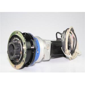
Yaskawa 0.75kW Servo Motor Single-phase 400W Industrial Servo Motor
SGMAH-08AAF41
QUICK DETAILS
Manufacturer: Yaskawa
Product number: SGMAH-08AAF41
Description: SGMAH-08AAF41 is an Motors-AC Servo manufactured by
Yaskawa
Servomotor Type: SGMAH Sigma II
Rated Output: 750W (1.0HP)
Power Supply: 200V
Output speed:5000 rpm
Torque rating:7.1 Nm
Minimum operating temperature:0 °C
Maximum operating temperature:+40 °C
Weight:8 lb
Height:3.15 in
Width:7.28 in
Depth:3.15 in
Encoder Specifications: 13-bit (2048 x 4) Incremental Encoder;
Standard
Revision Level: F
Shaft Specifications: Straight shaft with keyway (not available
with revision level N)
Accessories: Standard; without brake
Option: None
Type: none
OTHER SUPERIOR PRODUCTS
| Yasakawa Motor, Driver SG- | Mitsubishi Motor HC-,HA- |
| Westinghouse Modules 1C-,5X- | Emerson VE-,KJ- |
| Honeywell TC-,TK- | GE Modules IC - |
| Fanuc motor A0- | Yokogawa transmitter EJA- |
Similar Products
| SGMAH-04AAAHB61 |
| SGMAH-04ABA21 |
| SGMAH-04ABA41 |
| SGMAH-04ABA-ND11 |
| SGMAH-07ABA-NT12 |
| SGMAH-08A1A21 |
| SGMAH-08A1A2C |
| SGMAH-08A1A61D-0Y |
| SGMAH-08A1A6C |
| SGMAH-08A1A-DH21 |
| SGMAH-08AAA21 |
| SGMAH-08AAA21+ SGDM-08ADA |
| SGMAH-08AAA2C |
| SGMAH-08AAA41 |
| SGMAH-08AAA41+ SGDM-08ADA |
| SGMAH-08AAA41-Y1 |
| SGMAH-08AAA4C |
| SGMAH-08AAAH761 |
| SGMAH-08AAAHB61 |
| SGMAH-08AAAHC6B |
| SGMAH-08AAAYU41 |
| SGMAH-08AAF4C |
| SGMAH-A3A1A21 |
| SGMAH-A3A1A21+SGDM-A3ADA |
| SGMAH-A3A1A41 |
| SGMAH-A3A1AJ361 |
| SGMAH-A3AAA21 |
| SGMAH-A3AAA21-SY11 |
| SGMAH-A3AAA2S |
| SGMAH-A3AAAH761 |
| SGMAH-A3AAA-SY11 |
| SGMAH-A3AAA-YB11 |
| SGMAH-A3B1A41 |
| SGMAH-A3BAA21 |
| SGMAH-A3BBAG761 |
| SGMAH-A5A1A-AD11 |
| SGMAH-A5A1AJ721 |
| SGMAH-A5A1A-YB11 |
| SGMAH-A5A1A-YR61 |
Let's discuss why one might want to introduce an Integral factor
into the gain (A) of the control. The Bode diagram shows A
approaching infinity as the frequency approaches zero.
Theoretically, it does go to infinity at DC because if one put a
small error into an open loop drive/motor combination to cause it
to move, it would continue to move forever (the position would get
larger and larger). This is why a motor is classified as an
integrator itself - it integrates the small position error. If one
closes the loop, this has the effect of driving the error to zero
since any error will eventually cause motion in the proper
direction to bring F into coincidence with C. The system will only
come to rest when the error is precisely zero! The theory sounds
great, but in actual practice the error does not go to zero. In
order to cause the motor to move, the error is amplified and
generates a torque in the motor. When friction is present, that
torque must be large enough to overcome that friction. The motor
stops acting as an integrator at the point where the error is just
below the point required to induce sufficient torque to break
friction. The system will sit there with that error and torque, but
will not move.
The excitation sequences for the above drive modes are summarized
in Table 1.
In Microstepping Drive the currents in the windings are continuously varying to be able to break up one full step into many smaller discrete steps. More information on microstepping can be
found in the microstepping chapter. Torque vs, Angle Characteristics
In Microstepping Drive the currents in the windings are continuously varying to be able to break up one full step into many smaller discrete steps. More information on microstepping can be
found in the microstepping chapter. Torque vs, Angle Characteristics
The torque vs angle characteristics of a stepper motor are the relationship between the displacement of the rotor and the torque which applied to the rotor shaft when the stepper motor is energized at its rated voltage. An ideal stepper motor has a sinusoidal torque vs displacement characteristic as shown in figure 8.
Positions A and C represent stable equilibrium points when no external force or load is applied to the rotor
shaft. When you apply an external force Ta to the motor shaft you in essence create an angular displacement, Θa
. This angular displacement, Θa , is referred to as a lead or lag angle depending on wether the motor is actively accelerating or decelerating. When the rotor stops with an applied load it will come to rest at the position defined by this displacement angle. The motor develops a torque, Ta , in opposition to the applied external force in order to balance the load. As the load is increased the displacement angle also increases until it reaches the maximum holding torque, Th, of the motor. Once Th is exceeded the motor enters an unstable region. In this region a torque is the opposite direction is created and the rotor jumps over the unstable point to the next stable point.
MOTOR SLIP
The rotor in an induction motor can not turn at the synchronous speed. In order to
induce an EMF in the rotor, the rotor must move slower than the SS. If the rotor were to
somehow turn at SS, the EMF could not be induced in the rotor and therefore the rotor
would stop. However, if the rotor stopped or even if it slowed significantly, an EMF
would once again be induced in the rotor bars and it would begin rotating at a speed less
than the SS.
The relationship between the rotor speed and the SS is called the Slip. Typically, the
Slip is expressed as a percentage of the SS. The equation for the motor Slip is:
2 % S = (SS – RS) X100
SS
Where:
%S = Percent Slip
SS = Synchronous Speed (RPM)
RS = Rotor Speed (RPM)


Yaskawa 0.75kW Servo Motor Single-phase 400W Industrial Servo Motor SGMAH-08AAF41
Inquiry Cart
0