
Add to Cart
Feeders commonly used in the market, whether air feeders, roller
feeders, NC feeders, gear feeders or high-speed clip feeders, are continuous feeders designed for
sheet metal.
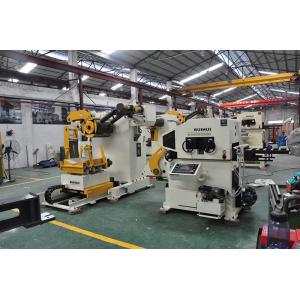
That is usually used on coils, the entire stamping automated
production line consists of unwinding device (material rack),
leveling device (leveling machine), feeding device (feeder),
punching machine and continuous die, receiving device (receiver) .
These devices are in turn arranged along the material feed
direction to form a complete automated stamping line.
In actual use, the coil material is placed on the material rack, and after it is unwound, it enters the leveling machine, and is
leveled and destressed by the leveling machine and then enters the
feeder.
In the stepping punching die through the feeder, the material is
punched and processed by the punching machine, and finally the
scraped waste is taken up and recovered by the receiving machine.
The sheet feeding machine is composed of four main functional
components: a feeding mechanism, a feeding mechanism, a pushing
mechanism and an electric control mechanism, and the actions of the
feeding mechanism, the feeding mechanism and the pushing mechanism
are all controlled by the electronic control component.
By simply setting the feed-related parameters on the touch panel of
the independent control box, the sheet can be accurately and
automatically fed into the punching position to achieve continuous
high-precision stamping production.
It not only saves stamping processing time, improves production
efficiency, but also fundamentally ensures the safety of stamping
processing.
When the sheet feeder is actually used, the motor output shaft of
the feeder feeding mechanism is connected to the screw drive
through the pulley.
The rotation of the screw rod can drive the loading shaft to move
up and down. When the feeding material moves in the axial
direction, the sheet disposed in the loading trough is sent to the
upper end of the loading trough.
The proximity sensor senses the sheet, the suction cylinder of the
feeding mechanism drives the vacuum suction head to move downward,
and the proximity switch disposed on one side of the feeding guide
shaft seat gives an inhalation signal.
The suction head sucks up the to-be-added part in the loading
trough, and when the vacuum suction head sucks the vacuum to be
added, the suction cylinder drives the upward movement. At this
time, the suction assembly is driven by the first servo motor. Move
forward.
The servo motor drives the pusher assembly forward, and the pusher
head of the pusher assembly pushes the sheet to the punch on the
front of the pusher guide axle seat.
After the completion of the action, the proximity switch disposed
on the side of the pusher guide shaft seat sends a signal to
return, the pusher assembly is reset, and the above work flow is
continuously repeated to complete the automated stamping process.
Specification:
| Model | MAC2-400 | MAC2-500 | MAC2-600 | MAC2-800 | ||
| Stock Width(mm) | 50-400 | 50-500 | 50-600 | 50-800 | ||
| Stock Thickness(mm) | 0.3~3.2 | 0.3-3.2 | 0.3-3.2 | -3.2 | ||
| Max.Coil Weight(kg) | 3000 | 3000 | 3000 | 5000 | 5000 | 7000 |
| Max.Coil O.D.(mm) | 1200 | 1200 | 1200 | |||
| Coil I.D.(mm) | 8 | 8 | 508 | 508 | ||
| Feed Length(mm) | ~500* | ~500* | ~500* | ~500* | ||
| Max. Line Speed(m/min) | 16-24 | 16-24 | 16-24 | 16-24 | ||
| Work Roll Number(pieces) | upper 6 lower 5 | upper 6 lower 5 | upper 6 lower 5 | upper 6 lower 5 | ||
| Feed Roll Number(set) | 1 | 1 | 1 | 1 | ||
| Main Motor(kw) | AC2.9 | AC2.9 | AC4.4 | AC4.4 | ||
| Mandrel Expansion | hydraulic | hydraulic | hydraulic | hydraulic | ||
| Reel Motor(kw) | 1.5 | 1.5 | 1.5 | 2.2 | 2.2 | 3.7 |
| Power(V) | 3 Phase 220V/380V/50HZ | |||||
| Operating Air(Mpa) | 0.49 | 0.49 | 0.49 | 0.49 | ||
Straigtening performance:
| tock Thicknees (mm) | Stock Width (mm) | |||
| 0.3 | 400 | 500 | 600 | 800 |
| 0.4 | ||||
| 0.6 | ||||
| 0.8 | ||||
| 1.0 | ||||
| 1.2 | ||||
| 1.4 | ||||
| 1.6 | 470 | 470 | ||
| 1.8 | 400 | 400 | ||
| 2.0 | 360 | 360 | ||
| 2.3 | 300 | 300 | 300 | 300 |
| 2.5 | 230 | 230 | 230 | 230 |
| 2.8 | 150 | 150 | 150 | 150 |
| 3.2 | 110 | 110 | 110 | 110 |
*1:(Pneumatic):Option in case of pneumatic mandrel expansion is
provi