
Add to Cart
1. Introduction
Hydraulic Power Station Spherical Valve (Also Named as Hydraulic
Power Station Ball Valve) is one of advanced control equipment
which installed at the inlet of the turbine in the world, and it’s
widely used as a out valve in irrigation works, power stations and
various pump stations, replacing non-return valve and gate valve.
While working, the valve cooperates with host computer of the
pipeline, according to the transition course principle of water
conservancy, through the procedure of opening and closing that is
preserved, dispel the pipeline water hammer effectively, realize
the ending reliably of the pipeline, and play a role in protecting
systematic security of pipeline.
Hydraulic Power Station Spherical Valve (Also Named as Hydraulic
Power Station Ball Valve) that our rechon vango valve produces
features with small flow resistence, high level of automation,
multifarious functions, steady and reliable performance. The valve
is a new generation’s intelligent energy-efficient product, which
designed by our company’s designers through collecting, studying,
summarizing the domestic and international similar properties of
product extensively, and introducing the multiple research results
of the valve, hydraulic pressure, and electric trade. Our company’s
technical force is rich, and the special requirement that can
follow users is designed alone, meet the masses of user’s
requirements for this kind of product diversely.
Hydraulic Power Station Spherical Valve (Also Named as Hydraulic
Power Station Ball Valve) mainly has the following characteristic:
It can replace the function of the electronic floodgate valve and
the non-return valve, which are at the exit of the pump. The
machine, electricity, liquid system integrates for one whole, as
well as it can reduce floor space and capital expenditure.
The electro-hydraulic control system has multifarious functions,
and it can debug, control locally as an independent systematic unit
without other additions. It also can be carried on centralized
management by the central computer through I/O passway as an
apparatus unit of the collecting and distributing control system
(DCS), realize linking and operating with water pump, hydraulic
turbine, by-pass valve and other pipelines apparatus. It is
furnished with manual function, and can turn on, turn off the valve
manually without power, meet valve debugging, control request under
the special operating mode.
The controllability is good, the regulation range and adaptability
is great. The electro-hydraulic control system has several
regulation points. It can open and close the valve according to
different pipeline control requests, so as to guarantee the valve
shut-off and open automatically according to time, angle that set
for in advance. In addition it can be closed without electricity,
effectively dispel the destructive water hammer; prevent water pump
and hydraulic turbine from splashing, the pressure fluctuation of
the pipe network system, guarantee equipment’s safe and reliable
operation.
The sealing pair of the main valve can be eccentric Type, It is
easy to open and close, and the sealing is reliable. It also has an
extra enlarge eccentric which makes the valve has a good function
of closing and sealing automatically. The ball of the middling and
small calibre Hydraulic Ball valve are designed with streamlined
dull and stereotyped structure, heavy-calibre disc is designed with
a pair of dull and stereotyped truss type structure, it is small to
squeeze, the stream is smooth-going, The energy-conserving result
is obvious.
2. Standards and Specifications
Note: When other related standards were used, they maybe noted in
the contractor or the technical agreement.
3. Basic parameters
Note: 1,1Mpa=10.2Kf/cO 2,When used in hydropower stations, it is
accordance with the highest static according to water-column to
calculate sealing test pressure
4. Special Parameters
5. Materials of Main Parts
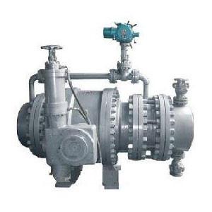
6. Product’s Structure
Hydraulic Power Station Spherical Valve (Also Named as Hydraulic
Power Station Ball Valve) is made up by the valve noumenonn,
actuator, hydraulic station, and electric control case.
Hydraulic Power Station Spherical Valve (Also Named as Hydraulic
Power Station Ball Valve) noumenonn is made up by valve body, disc,
shaft, transmission shaft and sealing package, etc.
The accumulator type generally adopts horizontal type; it can also
adopt vertical type according to user’s request.
The actuator is made up by the connection and transmission pieces
such as gear box, gear, rack, etcIt is the main executive body of
valve, which open and close the valve hydraulically.
The transmission hydraulic jar has slow -closing time adjusting
valveAdjusting range see item 5 (special parameters).
While fixed up horizontally, the actuator generally adopts obverse
installation. If there is not enough space, you can adopt reverse
installation (transmission device is placed on the other side of
valve body, see Fig. 4 – Fig. 5)
The hydraulic pressure station is made up by oil pump assembly,
hand operated pump, accumulator, electromagnetic valve, overflow
valve, flow control valve, stop valve, hydraulic pressure
integrated lump, oil tank, etc.
In accumulator type control system, the accumulators offer
initiative strength source for the fact that the valve is opened
and closed.
The flow control valve is used to adjust the time of opening the
valve. Adjusting range see item 5 (special parameters).
The hand operated pump is use for the systematic debugging and
opening and closing the valve under special operating mode.
The hydraulic systematic electromagnetic reversing valve generally
works in such a type, which is when the electromagnetic valve
connects with electricity, the butterfly valve works while do not
connect with electricity, the butterfly valve maintain the original
condition and is locked. This type is normal while other types
should be noticed when you make orderings.
The hydraulic system and valve noumenonn can install integrally, as
well as install separately. If users don’t have special
requirements, it is installed separately. When the accumulator type
is fixed up vertically, it should be installed separately
7. Electro-hydraulic Working Principle & Operation Notes (PLC
Type)
According to the logic components the electric control systemic
divided into common relay type and PLC intellectual control type.
The factory always formed a complete set of the common relay type,
and it should be proved while ordering the PLC intellectual control
type. The main operating modes of all kinds of divides are as
follows:
The operating mode of the opening valve’s eccentric pump (including
the centrifugal diagonal pump): Start the pump first, delay
scheduled time and turn on the valve, or open the pump and the
valve at the same time.
The operating mode of the opening valve’s axial pump (including the
axial-flow type diagonal pump): While opening the pump and the
valve at the same time, turn on the valve to some angle, and then
start the pump.
The operating mode of the operating mode of the hydraulic turbine
valve: Open the balanced pressure of the by-pass valve first, then
open the valve, and then open the hydraulic turbine.
This electric control system of the valve is furnished with local
controlling circuit and remote tandem controlling circuit. The
local controlling circuit is used to debugging in situ, while the
remote tandem controlling circuit is generally used to normal
working.
The systematic motive power is AC380V, the uninterrupted power
supply is DC220V, or other power grades( AC220V,,DC110V ,DC24V etc)
The hydraulic principle dewing see Appendix2,and The Electric
operation Principle dewing see Appendix1.
8. Automatic Pressure maintenance
When turn on the power switch QF1,QF2 ; the power indicator light
lights
Then change the transfer switch SW1 to ” Right” position, start the
automatic pressure maintaining system. The electric motor begins to
fill the accumulator with pressure. When the pressure reaches the
high-pressure switch’s setting number, the oil pump shuts
Maintenance is always in effect, in spite of which state the system
is on (Locale, remote, Down This function of automatic pressure
open, close, and etc Which is when the system drops the pressure to
low-pressure switch’s setting number, the oil pump will
automatically start to fill the pressure, when reach the
high-pressure switch’s setting number, it shuts down.
When the power of AC380V goes wrong, or the oil pump can’t work
normally, the pressure preserved in the accumulator can complete a
whole course of opening valve or closing valve.
You can release this function, through changing the transfer switch
SW1 to “Left” position
8.2 Locale Operation
Change the transfer switch SW2 to “Locale” position.
8.2.1 To open the valve
Press the open the valve locally button, if the motor does not have
trouble, conditions permit to open the valve, the electronic
by-pass valve is opened, and the pipeline excitatory transmitter
enters snail’s shell. The by-pass valve is opened and put in place,
the indicator lamp is bright, and the electrical motor shuts down.
If the both ends of the main valve’s pressure are balanced,
difference presses the changer SP signal to input, Opening
Electromagnetic Valve connects with the electricity and change the
direction., The hydraulic oil flow control valve, high-pressure
rubber pipes entered the oil cylinder, open the valve.
When opened the valve, the action switch is turned off, the
full-open indicator light lights, the electromagnetic valves all
loses electricity. the by-pass valve is closed automatically.
Through rotating the flow control valve can adjust the time of
opening the valve. You can change the time in order to meet the
practical operating mode.
8.2.2 To close the valve
Press the button of closing-valve, the indicator lamp of
closing-valve is bright, the by-pass valve is opened, and the
closing electromagnetic valve connects with the electricity and
change the direction. and the main valve close on the scheduled
speedWhen the valve is closed fully, it is stopped, and the
full-close indicator lamp lights, the closing-valve indicator lamp
goes out. the electromagnetic valves all loses electricity. the
by-pass valve is closed automatically.
Valve closing is divided into fast-close and slow-close. Through
rotating the flow valve and the slow-close flow valve at the tail
of cylinder you can adjust the speed.
8.2.3 Stop
You can discontinue movements through pressing the stop button in
the course of opening the valve or closing the valve normally. Let
the valve be stopped in the arbitrary position
8.3 Remote Operation
Place the change switch SA to “Remote”, and the remote control
indicator light lights. Then you can open the valve, close the
valve, and stop the valve separately at this moment.through the
remote switch .
In addition, the control system also outputs various state signals
for remote DCS to control. Such as valve position
(0º,15º,75º,90º),remote state, oil pump state, overload, overtime,
valve position 4~20mA signal, and etc.
8.4 Protections of losing the electricity
Under the general operating mode, when the motor works normally, if
the control system loses the electricity, electromagnetic valves
still maitain the original condition, in order to guarantees the
unit’s normal work.
8.5 Manual Operation
When the power of AC380V goes wrong , wave the hand operated
pumpyou can open and close the butterfly valve too.
Manual Operation is mainly used to debug the valve , or to close
the valve under special instance.
See notes on other operating modes and electro-hydraulic control
principle in our company’s pertinent (Install and operation
instructions).

