Common Mode (CM) Isolated Surge (BIS) semiconductor device /non-isolated LED drivers/surge circuit
Brand Name:Original
Certification:SGS.MA.CTI.CQC
Model Number:BIS-DS602
Minimum Order Quantity:10000PCS
Delivery Time:5-7 days
Payment Terms:T/T,Paypal,Western Union,Money gram
Contact Now
Add to Cart
Verified Supplier
Location:
Dongguan Guangdong China
Address:
Room 810, Unit 2, Building 5, Huixing Commercial Center, Dongsheng Road No.1, Zhongshan Dong, Shilong Town Dongguan, GUANGDONG, 523326 CN
Supplier`s last login times:
within 1 hours
Product Details
Company Profile
Product Details
Description:
Common Mode (CM) Uchi Isolated Surge (BIS) protection device is a
semiconductor device developed for surge
protection requirements of non-isolated LED drivers. Solution of
BIS series connecting with MOVs can meet both
isolation requirements and surge protection requirements. For class
I LED devices, isolation requirement of electrical
strength is 1000V+2U (U is rated work Voltage), this means the
surge protections solutions should have peak
reverse voltage rated up to 1000V+2U, and thus the residual voltage
is very high under 4KV or 6KV 1.2/50us &8/
20us surge waves for both L-PE and N-PE lines. Boarden CM BIS
products family can significantly reduce the
residual voltage hence protect the LED driver safe and reliable.
Features:
1. Meeting both insolation requirement and surge protection
requirements
2.Long life under repetitive surges
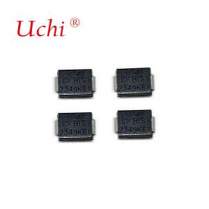
3.Package: SMB,DO-27
4.High Working Voltages
5.Bi-directional
6.RoHS compliant
7.TUV Rheinland Certificate: R50442482
Order Information:
| Package | Qty per Reel | Tape |
SMB | 3000 | 13'' Reel |
DO-27 | 1250 | Box |
Maximum Ratings and Thermal Characteristics (TA=25°C unless
otherwise noted)
Device Ratings and Specifications (Tamb=25℃)
Product Dimensions (mm)
Marking System
Common-mode BIS surge circuit optimization
1-1The shunt resistance has two functions.
1. Pressure stabilization: due to the existence of resistance, the
voltage at both ends of the BIS cannot be sharply changed, so as to
reduce the dv / dt induced by the test line, and effectively avoid
the gate trigger;
2. Pressure equalization: in the section less than the action
voltage, the equivalent impedance of BIS is far greater than the
impedance of MOV. Therefore, in the process of voltage resistance
test, the voltage is basically added at both ends of the BIS at the
beginning, and then as the leakage current increases, MOV gradually
shares the voltage. Increase the resistance of level MΩ (the same
magnitude as the impedance of the MOV), then the partial pressure
of MOV and BIS will be more balanced, and the test will be more
stable. Capacitance only voltage stability without poor
equalization, so parallel resistance is recommended as compensation
improvement.
3. The larger the Y capacitor of drive L and N to the ground, the
greater the interference of the inductance in the stabilizer, and
the greater the shadow leads to BIS. It is understood that the
current drive internal use of 222Y capacitor is more.102Y capacitor
is much smaller than 222Y capacitor.
Patch Resistance (color source):
1-2 Safety regulation resistance
Resistance used for grounding shall meet the IEC / UL 60065 (the
new version is IEC / UL 62368-1 2018) standard.
Protocol requirements for a linear DOB:
In addition to the combined resistance on both ends of the BIS, the
pressure resistance of the aluminum substrate needs to be
evaluated.
Because IC and lamp beads and other devices are mounted on the
aluminum substrate, because the BIS conduction will also have the
residual pressure of the device, the poor pressure resistance of
the aluminum substrate will be different to the IC or lamp beads
will be
damaged when the test common mold surge. Therefore, the withstand
pressure of the substrate needs to reach 3000VAC (the insulation
layer
should reach 120um-180um). Only the aluminum substrate and BIS
cooperate can solve the surge performance.
Note:
The above common mode BIS surge scheme is built in theswitch
non-isolation, isolation, linear scheme both ends of the BIS need
and safety regulation resistance or capacitor or RC circuit three
voltage equalization scheme can be, enhance the reliability of
voltage resistance. RV1 and RV2 are sensitive according to the test
voltage tolerance of each customer, and the recommended voltage
range is between 680V and 1300V.
Linear DOB and non-isolated drive suggest an aluminum substrate of
3000 Vac.


Common Mode (CM) Isolated Surge (BIS) semiconductor device /non-isolated LED drivers/surge circuit
Inquiry Cart
0