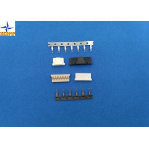
DF14 wire connector crimp terminals with 1.25mm pitch, gold-flash phosphor bronze terminals
Brand Name:HRT
Certification:ISO9001/ ISO14001/UL/RoHS/REACH
Model Number:A1253-T
Minimum Order Quantity:75KPCS
Delivery Time:5 to 8 working days after payment checked
Payment Terms:TT, Western Union, PayPal, L/C
Contact Now
Add to Cart
Verified Supplier
Location:
Shenzhen Guangdong China
Address:
No.A1507H2 Xinhe Century Building, 3069 Caitian Rd, Gangxia Community, Futian District, Shenzhen City, China
Supplier`s last login times:
within 24 hours
Shipping
lt's easy to get a shipping quote! Just click the button below and complete the short form.
Get Shipping Quote
Product Details
Company Profile
Product Details
Pitch 1.25mm Tin-plated or Gold- flash wire connector terminal
Category: Crimp Terminals
Series:A1253-TPEor A1253-GPE
Application:Signal
Material :Phosphor Bronze
Finish:Tin-plated or Gold-flash
Packaging Type: Reel
Termination Interface Style: Crimp or Compression
Wire Insulation Diameter:1.00mm(max)
Electrical & Mechanical information:
Current Rating: 1A AC, DC
Voltage Rating: 150V AC, DC
Contact Resistance: 30mΩ Max
Insulation Resistance:500MΩ Min
Withstanding Voltage: 500V AC/minute
Temperature range: -25℃ to 85 ℃
Ordering Information:
| Part No. | Wire Range | Insulation O.D. | Material | Finish | Qty/reel |
| A1252-TPE | AWG26#-32# | 1.00mm(Max) | Phosphor Bronze | Tin-plated | 15Kpcs/reel |
| A1252-GPE | Gold-flash | ||||
| Note: | E-stamping before tin-plated or Gold-flash | ||||
Drawing & testing report:
Please kindly check the following information to order right products.
1. Scope This specification covers the requirements for product performance of 2.00mm pitch wire to board connectors series. 2. Construction,Dimensions,Material & Plating See the attached drawings 3. Ratings & Applicable Wires
*: Including terminal temperature rise 4. Electrical Performance
5. Mechanical Performance
| ||||||||||||||||||||||||||||||||||||||||||||||||||||||||||||||||||||||||||||||||||||||||||||||||||||||||||||||||||||||||||||||||||
6. Environmental Performance And Others
7. Crimp Specifications & Actuator Insertion/Withdrawal Force 7-1 Terminals with height, suggestion pressure width and wire and terminal's retention
7-2 [Unit : kgf]
| ||||||||||||||||||||||||||||||||||||||||||||||||||||||||||||||||||||||||||||||||||||||||||||||||||||||||||||||||||||||||||||||||||

DF14 wire connector crimp terminals with 1.25mm pitch, gold-flash phosphor bronze terminals
Inquiry Cart
0