Ethernet SFP Optical Fiber Transceiver Module 100g BASE LR4 / OTU4 CFP2 LR4
Brand Name:E-link China
Certification:CE, RoHS, FCC
Model Number:LNK-CFP2-LR4-10KM
Minimum Order Quantity:1 piece
Delivery Time:3-5 working days
Payment Terms:T/T, Western Union, MoneyGram, Paypal
Contact Now
Add to Cart
Verified Supplier
Location:
Shenzhen Guangdong China
Address:
5F, Building D South, Jinshenghui Science Park, No. 3, Dafu Road, Fucheng Street, Guanlan, Longhua District, Shenzhen, China
Supplier`s last login times:
within 16 hours
Shipping
lt's easy to get a shipping quote! Just click the button below and complete the short form.
Get Shipping Quote
Product Details
Company Profile
Product Details
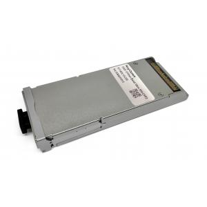
100GBASE-LR4 and OTU4 CFP2 LR4 10km SFP Optical Transceiver Module
PRODUCT FEATURES
- Duplex LC receptacle optical interface
- Single +3.3V power supply
- Hot-pluggable
- Operating optical data rate up to 112Gbps
- Operating electrical serial data rate up to 27.952493Gbps
- 4 parallel electrical serial interface
- AC coupling of CML signals
- PIN ROSA
- Low power dissipation(Max:9W)
- Built in digital diagnostic function
- Operating case temperature range:0℃ to 70℃
- Compliant with 100GBASE-LR4 and OTU4
- MDIO Communication Interface
- Compatible with all kinds of commercial ONT
APPLICATIONS
- Local Area Network(LAN)
- Wide Area Network(WAN)
- Switch to router interface
- ITU-T OTU4 OTL4.4 applications
Standards
- Compliant with IEEE 802.3ba
- Compliant with CFP2 MSA hardware specifications
- Compliant with CFP2 MSA management specifications
- Compliant with ITU-T G709/Y.1331
- Compliant with RoHS
Functional Description
The 100G CFP2 LR4 optical transceiver integrates the transmit and receive path onto one module. On the transmit side, four lanes of serial data streams are recovered, retimed,and passed on to four laser drivers, which control four electric-absorption modulated lasers (EMLs) with 1296, 1300, 1305, and 1309 nm center wavelengths. The optical signals are then multiplexed into a single-mode fiber through an industry-standard LC connector.On the receive side, four lanes of optical data streams are optically demultiplexed by an integrated optical demultiplexer. Each data steam is recovered by a PIN photodetector and transimpedance amplifier, retimed, and passed on to an output driver. This module features a hot-pluggable electrical interface, low power consumption, and MDIO management interface.
Absolute Maximum Ratings
| Parameter | Symbol | Min | Typ | Max | Units | Notes |
| Storage Temperature | Tst | -40 | +85 | ºC | ||
| Supply Voltage | Vcc | -0.5 | +3.6 | V | ||
| Operating Relative Humidity | Rh | +5 | +95 | % |
Recommended Operating Conditions
| Parameter | Symbol | Min | Typ | Max | Units | Notes |
| Operating Case Temperature | TC | 0 | - | +70 | °C | |
| Power Supply Voltage | VCC | 3.14 | 3.3 | 3.46 | V | |
| Data rate | 103.125 | 112 | Gb/s |
Specifications
(tested under recommended operating conditions,unless otherwise noted)
| Parameter | Symbol | Unit | Min | Typ | Max | Notes | |||||||||
| Voltage Supply Electrical Characteristics | |||||||||||||||
| Supply Current | Tx Section | Icc | A | 3.75 | 1 | ||||||||||
| Rx Section | |||||||||||||||
| Power Supply Noise | Vrip | 2% DC | 1MHz | ||||||||||||
| 3% 1 | 10MHz | ||||||||||||||
Total Dissipation Power | Class1 | Pw | W | 3 | |||||||||||
| Class2 | 6 | ||||||||||||||
| Class3 | 9 | ||||||||||||||
| Class4 | 12 | ||||||||||||||
| Low Power Mode Dissipation | Plow | W | 2 | ||||||||||||
| Inrush Current | Class1 | and | I-inrush | mA/usec | 100 | ||||||||||
| Turn-off Current | Class2 | I-turnoff | mA/usec | -100 | |||||||||||
| Inrush Current | Class3 | and | I-inrush | mA/usec | 200 | ||||||||||
| Turn-off Current | Class4 | I-turnoff | mA/usec | -200 | |||||||||||
| Different Signal Electrical Characteristics | |||||||||||||||
| Single Ended Data Input Swing | mV | 20 | 525 | ||||||||||||
| Single Ended Data Output Swing | mV | 180 | 385 | ||||||||||||
Differential Signal Output Resistance | Ω | 80 | 120 | ||||||||||||
Differential Signal Input Resistance | Ω | 80 | 120 | ||||||||||||
| 3.3V LVCMOS Electrical Characteristics | |||||||||||||||
| Input High Voltage | 3.3VIH | V | 2.0 | Vcc+0.3 | |||||||||||
| Input Low Voltage | 3.3VIL | V | -0.3 | 0.8 | |||||||||||
| Input Leakage Current | 3.3IIN | uA | -10 | +10 | |||||||||||
Output High Voltage (IOH=100uA) | 3.3VOH | V | Vcc-0.2 | ||||||||||||
| Output Low Voltage (IOL=100uA) | 3.3VOL | V | 0.2 | ||||||||||||
Minimum Pulse Width of Control Pin Signal | t_CNTL | us | 100 | ||||||||||||
| 1.2V LVCMOS Electrical Characteristics | |||||||||||||||
| Input High Voltage | 1.2VIH | V | 0.84 | 1.5 | |||||||||||
| Input Low Voltage | 1.2VIL V | 0.3 | 1.2VIL V | 0.36 | |||||||||||
| Input Leakage Current | 1.2IIN | uA | -100 | +100 | |||||||||||
| Output High Voltage | 1.2VOH | V | 1.0 | 1.5 | |||||||||||
| Output Low Voltage | 1.2VOL | V | -0.3 | 0.2 | |||||||||||
| Output High Current | 1.2IOH | mA | -4 | ||||||||||||
| Output Low Current | 1.2IOL | mA | +4 | ||||||||||||
| Input Capacitance | Ci | pF | 10 | ||||||||||||
| Optical Transmitter Characteristics | |||||||||||||||
| Signaling rate, each lane | GBd | 25.78125 ±100 ppm | 100GBase-LR4 | ||||||||||||
| 27.9525 ±20 ppm | OTU4 | ||||||||||||||
| Four Lane Wavelength Range | λ1 | nm | 1294.53 | 1295.56 | 1296.59 | ||||||||||
| λ2 | 1299.02 | 1300.05 | 1301.09 | ||||||||||||
| λ3 | 1303.54 | 1304.58 | 1305.63 | ||||||||||||
| λ4 | 1308.09 | 1309.14 | 1310.19 | ||||||||||||
| Total launch power | dBm | 10.5 | 100GBase-LR4 | ||||||||||||
| 10 | OTU4 | ||||||||||||||
| Average launch power, each lane | Pavg | dBm | -4.3 | 4.5 | 2 | ||||||||||
| -0.6 | 4 | ||||||||||||||
| Optical modulation amplitude, each lane (OMA)2 | OMA | dBm | -1.3 | 4.5 | |||||||||||
| Difference in launch power between any two lanes (OMA) | dB | 5 | |||||||||||||
| Extinction ratio | ER | dB | 4 | 100GBase-LR4 | |||||||||||
| 4 | 6.5 | OTU4 | |||||||||||||
| Side-mode suppression ratio | SMSR | dB | 30 | ||||||||||||
| Transmitter and dispersion penalty, each lane | TDP | dB | 2.2 | ||||||||||||
| Optical return loss tolerance | dB | 20 | |||||||||||||
| Transmitter reflectance3 | dB | –12 | |||||||||||||
| Transmitter eye mask {X1, X2, X3, Y1, Y2, Y3} | {0.25, 0.4, 0.45, 0.25, 0.28, 0.4} | 100GBase-LR4 | |||||||||||||
| Optical Receiver Characteristics | |||||||||||||||
| Receive Rate for Each Lane | Gbps | 25.78125 | 27.9525 | ||||||||||||
| Overload Input Optical Power | Pmax | dBm | 5.5 | 3 | |||||||||||
Average Receive Power for Each Lane | Pin | dBm | -8.6 + ∆ | 3 | 4, 5, 9 | ||||||||||
Receive Power In OMA for Each Lane | PinOMA | dBm | 3 | ||||||||||||
Difference in Receive Power in OMA between Any Two Lanes | dBm | ||||||||||||||
Receiver Sensitivity in OMA for Each Lane | SOMA | dBm | -8.6 + ∆ | 6 | |||||||||||
Stressed Receiver Sensitivity in OMA for Each Lane | dBm | -6.8 + ∆ | 7, 8, 9 | ||||||||||||
Note1. The supply current includes CFP2 module’s supply current and test board working
current.
Note2. Average launch power, each lane (min) is informative for 100GBase-LR4, not the principal indicator of signal strength.
Note3.The receiver shall be able to tolerate , without damage, continuous exposure to an
optical input signal having this average power level
Note4. The average receive power , each lane (max) for 100GBASE-ER4 is larger than the
100BASE-ER4 transmitter value to allow compatibility with 100BASE-LR4 units at short
distances
Note5. Average receive power, each lane (min) is informative and not the principal indicator
of signal strength. A received power below this value cannot be compliant; however, a value
above this does not ensure compliance
Note6. Receiver sensitivity (OMA), each lane (max) is informative
Note7. Measured with conformance test signal at TP3 for BER=10-12
Note8. conditions of stressed receiver sensitivity test: vertical eye closure penalty for each
lane is 1.8dB;stressed eye J2 jitter for each lane is 0.3UI; stressed eye J9 jitter for each lane
is 0.47UI.
Note9. ∆ = ADP ROSA sensitivity (a negative number) - (-8.6dBm) - (-1.9dB (DeMUX insertion loss)) - δ (a negotiable additional loss).


Ethernet SFP Optical Fiber Transceiver Module 100g BASE LR4 / OTU4 CFP2 LR4
Inquiry Cart
0