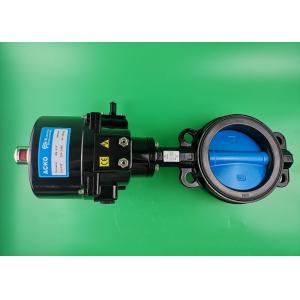
Solenoid Electric Butterfly Valve Wafer Type Air Flow Control 220Vac 50 60 Hz
Brand Name:ACKO
Certification:CE ISO
Model Number:VA16-50-O1;VA16-50-M1
Minimum Order Quantity:Negotiation
Delivery Time:7-14 working days
Payment Terms:T/T
Contact Now
Add to Cart
Active Member
Location:
Shanghai Shanghai China
Address:
No.277 Zheqiao Rd. Pudong New District,Shanghai China
Supplier`s last login times:
within 22 hours
Shipping
lt's easy to get a shipping quote! Just click the button below and complete the short form.
Get Shipping Quote
Product Details
Company Profile
Product Details
Solenoid High Pressure Wafer Type Electric Butterfly Valve Air Flow Control 220Vac 50/60 Hz
OVERVIEW
Lug Style Butterfly Valves
Lug-style valves have mounting threads on both sides of the valve body. This allows the lug butterfly valve to be installed into a system using two sets of bolts and no nuts. The valve is installed between two ANSI/ASME pipe flanges with a separate set of bolts for each flange.
Electric Actuated Butterfly Valves
Electric Actuated Butterfly Valves
Valworx electric actuators rotate an output drive to open and close
butterfly valves. Electric actuators provide a reliable and
economical method of operating these valves from a remote location.
For modulating valve applications, an electric actuator with EPS
positioning can control the valve flow with a 4-20mA command
signal.
Air Actuated Butterfly Valves
Air Actuated Butterfly Valves
Rack and pinion quarter turn air actuators provide a simple and
reliable method of automating butterfly valves. Actuators are
available in spring return or double acting. Spring return
actuators use air pressure to open and springs to close the valve
(failsafe). A double acting air actuator uses air to open and air
to close.
Manual Butterfly Valves
Manual Butterfly Valves
Butterfly valves are used to control flow in a pipe line. Rotating
a disc within the valve body 90° opens or closes the flow passage.
The butterfly valve can be operated with the 10-position locking
hand lever. Butterfly valves are mounted between two pipe flanges
for easy installation and maintenance.
FEATURES
• Wide size range (DN 50…DN600)
• For On-Off or Modulating Control
• The handwheel assembly manual adjustment
• Irreversible worm gear.
• Visual mechanical position indicator for accurate visual
reference of valve position.
• Anti-condensation heater and 2 aux. limit switches on standard
model
• Enclosure IP67
SPECIFICATIONS:
Table (1) Control Type and Valve Size Data
The below table is based on differential pressure of 10 bar.
| Valve | Model | Model | Model | Model | Torque | Run Time | Power | Manual | Kvs |
| Size | (On-Off) | Actuator | (Modulating) | Actuator | (Nm) | at 60Hz | (Watts) | Override | (m3/h) |
| (sec) | |||||||||
| DN50 | VA16-50-O1 | AK-O1 | VA16-50-M1 | AK-M1 | 50 | 11 | 10 | / | 109 |
| DN65 | VA16-65-O1 | AK-O1 | VA16-65-M1 | AK-M1 | 50 | 11 | 10 | / | 177 |
| DN80 | VA16-80-O1 | AK-O1 | VA16-80-M1 | AK-M1 | 50 | 11 | 10 | / | 243 |
| DN100 | VA16-100-O2 | AK-O2 | VA16-100-M2 | AK-M2 | 100 | 18 | 40 | Hand-wheel | 483 |
| DN125 | VA16-125-O2 | AK-O2 | VA16-125-M2 | AK-M2 | 100 | 18 | 40 | Hand-wheel | 822 |
| DN150 | VA16-150-O3 | AK-O3 | VA16-150-M3 | AK-M3 | 200 | 18 | 40 | Hand-wheel | 1270 |
| DN200 | VA16-200-O3 | AK-O3 | VA16-200-M3 | AK-M3 | 200 | 28 | 40 | Hand-wheel | 2550 |
| DN250 | VA16-250-O4 | AK-O4 | VA16-250-M4 | AK-M4 | 400 | 28 | 120 | Hand-wheel | 4342 |
| DN300 | VA16-300-O6 | AK-O6 | VA16-300-M6 | AK-M6 | 650 | 34 | 120 | Hand-wheel | 6708 |
| DN350 | VA16-350-O7 | AK-O7 | VA16-350-M7 | AK-M7 | 1000 | 45 | 180 | Hand-wheel | 9793 |
| DN400 | VA16-400-O8 | AK-O8 | VA16-400-M8 | AK-M8 | 1500 | 45 | 220 | Hand-wheel | 13467 |
| DN450 | VA16-450-O9 | AK-O9 | VA16-450-M9 | AK-M9 | 2000 | 56 | 180 | Hand-wheel | 17836 |
| DN500 | VA16-500-O10 | AK-O10 | VA16-500-M10 | AK-M10 | 3500 | 58 | 220 | Hand-wheel | 22933 |
| DN600 | VA16-600-O10 | AK-O10 | VA16-600-M10 | AK-M10 | 3500 | 58 | 300 | Hand-wheel | 35431 |
Figure (1) Product Identification System
The labeling system is as follows:
Table (2) Valve Dimensions (mm) and Weight
| Size | L1 | L2 | 4-Ø2 | 4-Ø3 | Øb | D1 | D2 | D3 | K×K | H3 | H2 | H1 | Weight (Kg) | |
| DN | Inch | |||||||||||||
| 50 | 2” | 42 | 32 | 22 | 4-7 | 50 | 125 | 96.5 | 72 | 15 | 130 | 70 | 2.36 | |
| 65 | 2.5” | 45 | 47 | 22 | 4-7 | 50 | 145 | 110 | 72 | 11×11 | 15 | 142 | 80 | 2.5 |
| 80 | 3” | 45 | 65 | 23 | 4-7 | 50 | 160 | 124 | 72 | 11×11 | 26 | 155 | 92 | 2.84 |
| 100 | 4” | 52 | 91 | 27 | 4-10 | 70 | 180 | 158 | 92 | 14×14 | 26 | 170 | 107 | 4.41 |
| 125 | 5” | 55 | 112 | 25 | 4-10 | 70 | 210 | 187 | 92 | 14×14 | 26 | 190 | 121 | 6.1 |
| 150 | 6” | 56 | 146 | 24 | 4-10 | 70 | 240 | 214 | 92 | 17×17 | 26 | 210 | 134 | 7.46 |
| 200 | 8” | 61 | 194 | 24 | 4-12 | 70 | 295 | 266 | 125 | 17×17 | 30 | 243 | 170 | 12.2 |
| 250 | 10” | 66 | 242 | 31 | 4-12 | 102 | 355 | 325 | 125 | 22×22 | 30 | 282 | 208 | 19.35 |
| 300 | 12” | 77 | 192 | 32 | 4-14 | 102 | 410 | 380 | 150 | 22×22 | 30 | 307 | 240 | 28.1 |
| 350 | 14” | 77 | 325 | 34 | 4-14 | 125 | 470 | 422 | 150 | 27×27 | 36 | 345 | 265 | 39 |
| 400 | 16” | 87 | 380 | 30 | 4-18 | 140 | 525 | 473 | 175 | 36×36 | 40 | 377 | 297 | 58 |
| 450 | 18” | 105 | 428 | 32 | 4-18 | 140 | 585 | 526 | 175 | 36×36 | 40 | 412 | 331 | 72 |
| 500 | 20” | 130 | 474 | 33 | 4-22 | 165 | 650 | 577 | 210 | 46×46 | 50 | 440 | 361 | 128 |
| 600 | 24” | 152 | 573 | 36 | 4-18 | 254 | 770 | 693 | 300 | 46×46 | 50 | 562 | 459 | 178 |
Table (3a)Actuator Dimensions (mm)
| OS# | A | B | C | D | E | F | G | M |
| O1 | 114 | 8 | 115 | 155/185 | 14×14×15 | 50 | M6·12 | 60 |
With Modulating Card D=185
No mechanical stops
Table (b) Actuator Dimensions(mm)
Table (c) Actuator Dimensions(mm)
AK-O7 to AK-O12
| OS# | A | B | C | D | E | F | G | M |
| O7,8,9 | 180 | 325 | 230 | 475 | 36×36×40 | 125 | M12·45 | 180 |
| O10,12 | 300 | 450 | 230 | 475 | 54×54×72 | 165 | M18·50 | 300 |


Solenoid Electric Butterfly Valve Wafer Type Air Flow Control 220Vac 50 60 Hz
Inquiry Cart
0