Epoxy Resin Cast Zero Sequence Current Transformer Split Core Type High Voltage
Brand Name:GFUVE
Certification:CE, ISO9001
Model Number:LZCK2500-10
Minimum Order Quantity:3PCS
Delivery Time:3-7days
Payment Terms:L/C, D/A, D/P, T/T, Western Union, MoneyGram
Contact Now
Add to Cart
Verified Supplier
Location:
Beijing Beijing China
Address:
Oriental HuaRui A, No. 150 Guanzhuang Road, Chaoyang District, Beijing, 100024, China
Supplier`s last login times:
within 37 hours
Shipping
lt's easy to get a shipping quote! Just click the button below and complete the short form.
Get Shipping Quote
Product Details
Company Profile
Product Details
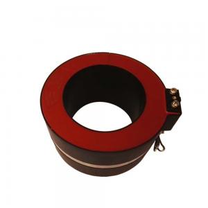
120mm High Voltage Cast Epoxy Resin Split Core Zero Sequence
Current Transformer
Theory
Current transformers typically consist of a silicon steel ring core
wound with many turns of copper wire as shown in the illustration
to the right. The conductor carrying the primary current is passed
through the ring. The CT's primary, therefore, consists of a single
'turn'. The primary 'winding' may be a permanent part of the
current transformer, i.e. a heavy copper bar to carry current
through the core. Window-type current transformers (aka zero
sequence current transformers, or ZSCT) are also common, which can
have circuit cables run through the middle of an opening in the
core to provide a single-turn primary winding. To assist accuracy,
the primary conductor should be centered in the aperture.
Applications
LZCK2500-10 zero sequence current transformer is suitable for
current measurement and microcomputer protection of electrical
equipment in 10KV and 35KV AC power system. It is widely used in
compact fully insulated ring network switchgears such as ABB-Safe
Ring/Safe Plus...and cable distribution boxes. The current
transformer can be directly installed at the inlet andoutlet
cables.The slice is imported silicon material. Thesemicircular ring
core and secondary windings
zero sequence current transformer is mainly measurement current for
Protection device
Features
New magnetic material is taken to be the core of the current
transformer, which has high magnetic permeability, low saturation
magnetization and good stability. Therefore, the measuring accuracy
is higher and the instrument security factor is lower. Since the
high quality silicon processed by advanced technology is taken to
be the core of the protection windings, which assured the accuracy
limit factor is higher.
The semicircular ring core and secondary windings are vacuum poured
by high quality epoxide resin in the fire retardant plastic casing,
which has the characteristic of moisture proof, stable performance
and dispensing with maintenance.Small size, light weight, small
footprint, fixed in the ring network switchgear cable.The cable can
cross the current transformer through its internal poles quickly
and uniformly.
The Cast Resin Straight-Through Current Transformer can be divided
several kinds according to the various current ratio, accuracy and
rated loads. The specific parameters are showed in the
corresponding to each model parameter tables.
PARAMETERS
| Technical parameters | |
|---|---|
| Standards | IEC60044-1; IEC 61869-2; NTC 2205; ANSI C57.13; GB1208-2006 |
| Rated primary current | 100-1500A |
| Rated load | ≤20VA |
| Rated frequency | 50Hz or 60Hz |
| Rated secondary current | 5A or 1A |
| Rated short-time thermal current | 40kA, 1S |
| Rated continuous thermal current | 120%I1n |
| Secondary winding power-frequency voltage | 3kV, 1min |
| Instrument security factor | FS≤10 |
| Mechanical parameters | |
| Dimensions (W×D×H) (mm) | φ120xφ185x100 |
| Weight (kg) | 7 |
| Operating conditions | |
| Operating temperature | -35°C to +55°C |
| Daily average temp | <+40°C |
| Storage temperature | -40°C to +70°C |
| Altitude | <3500 meters |
| Condition | No existence of severely begrimed, erosive and radioactive gas in the air. Permission of long-term operation under rated current. |
SELECTION GUIDE
| Type | LZCK2500-10 | LZCK2500-10 | ||||
|---|---|---|---|---|---|---|
| Purpose | Measuring current transformer | Protection current transformer | ||||
| Ratio | Accuracy class and rated load(VA) | Accuracy class and rated load(VA) | ||||
| I1/I2 | 0.5 | 1 | 3 | 10P15 | 10P10 | 10P5 |
| 300/5 | 5 | 5 | 5 | 2.5 | 5 | 7.5 |
| 400/5 | 5 | 5 | 5 | 2.5 | 5 | 7.5 |
| 500/5 | 5 | 7.5 | 7.5 | 5 | 7.5 | 10 |
| 600/5 | 5 | 7.5 | 7.5 | 5 | 7.5 | 10 |
| 800/5 | 10 | 10 | 10 | 5 | 10 | 15 |
| 1000/5 | 10 | 15 | 15 | 5 | 10 | 15 |
| 1200/5 | 15 | 20 | 20 | 10 | 15 | 20 |
| 1500/5 | 15 | 20 | 20 | 10 | 15 | 20 |
SELECTION GUIDE
| Model | Primary rated current | Rated load | Aperture (mm) | Description (mm) | Weight (kg) | Material | Water-proof |
|---|---|---|---|---|---|---|---|
| LZCK-55 | 100-1500A | ≤10VA | φ55 | 180×138×52 | 2 | ABS+Resin | IP65 |
| LMCK185-10 | 300-3000A | ≤25VA | φ185 | 350×283×55 | 4.5 | ABS+Resin | IP65 |
| LZCK310-10 | 300-600A | ≤10VA | φ50 | φ50 x φ110 x 32 | 1 | Resin | silicon case (option) |
| LZCK322-10 | 30-600A | ≤10VA | φ50 | φ50 x φ110 x 52 | 1.6 | Resin | silicon case (option) |
| LZCK350-10 | 20-600A | ≤25VA | φ50 | φ50 x φ110 x 105 | 3.1 | Resin | silicon case (option) |
| LZCK720-10 | 20-1000A | ≤25VA | φ60 | φ80 x φ110 x 50 | 2.1 | Resin | silicon case (option) |
| LZCK2500-10 | 500-1500A | ≤20VA | φ120 | φ120 x φ185 x 100 | 7 | Resin | silicon case (option) |
| LZCG530-10 | 30-600A | ≤20VA | φ45 | φ45 x φ120 x 65 | 2.1 | Resin | silicon case (option) |
| LZCG930-10 | 100-1500A | ≤25VA | φ60 | φ60 x φ155 x 60 | 3.6 | Resin | silicon case (option) |
| LZCT722-10 | 20-600A | ≤10VA | φ82 | φ82 x φ130 x 55 | 2.3 | Resin | silicon case (option) |
WIRING DIAGRAMS
P1, P2 is primary polarity terminal, S1, S2 is secondary polarity
terminal.
P2, S2 is homonymous terminals (subtractive polarity).

Epoxy Resin Cast Zero Sequence Current Transformer Split Core Type High Voltage
Inquiry Cart
0