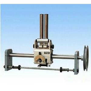
Rolling Ring Linear Drive
Model Number:PX
Minimum Order Quantity:1set
Delivery Time:ASAP
Payment Terms:T/T
Place of Origin:China
Price:negotiate
Contact Now
Add to Cart
Active Member
Address:
Industrial Park, Xindai Town, pinghu,Zhejiang
Supplier`s last login times:
within 48 hours
Shipping
lt's easy to get a shipping quote! Just click the button below and complete the short form.
Get Shipping Quote
Product Details
Company Profile
Product Details
Product Brief Introduction
we can provide a wide range of smooth shaft(rolling rings) traverse drives with different types,which can meet various requirements of our customers.among our products,the types PX15-PX30,with housings of aluminium alloy,have 3-frame and 4-frame models respectively,the thrust force of the 4-frame model doubling that of the 3-frame one. PX40 and PX50 have 2 models,one with the aluminium alloy housing and the other with the cast iron one. And PX60 is of the cast iron housing. The housings made of cast iron have good rigidity and reliablepositioning,being applicable to the applications which are under the severe environmental conditions and require large thrust force.
The rolling ring linear drives provided by us are characterized wuth a lot of features such as the stepless speed adjustment,the instantaneous reversal, the Drive position adjustment just by means of the release lever,the special treatment of the Smooth Shaft,the Traverse Drive being mounted with selected high performance bearings,and long service life.
Installation and Debugging
Release Lever. There are two positions,i.e, the working position "1" and the releasing position "0". When the lever sits at the working position,the bearing above it are at the lifting position and apply pressure to the Smooth Shaft and so make the Traverse Drive generate the thrust force.when the lever sits at the Releasing Position,the earings above it are at the falling position and by pushing with hands you can make the Traverse Drive slide freely on the Smooth Shaft.Before install the Smooth Shaft,pull the Release Lever and check if the bearings can be moved up and down.
Mounting the Smooth Shaft By putting the Release Lever at the released position"0" and adjusting the sheathes at the both sides of drive you can install the shaft into the Traverse Drive,and then pull the Release Lever to the working position"1"
Adjusting the Guide Roller The Guide Rollers can be used to ensure the working stability of the Traverse Drive.The Guide Frame is eccentric.when the space between the Guide Roller and the Guide Bar is not correct,adjustment can be made by loosing the screws and turning the Guide Frame.
Determining Direction of Rotation The downward turning of the shaft when facing the scale dial is defined as the positive rotation,in which case the trigger roller of the reverseal arm shall point to the side where the scale dial is.While the upward turning of the shaft when you looking in front of scale dial is reverse rotation and in such case the trigger roller of the reversal arm shall point to the backward side of the traverse housing so that the reversal of the traverse drive can be realized. The roduct is normally assembled with the shaft turning positively when leaving the factory.
Rotation Speed of Shaft The take-up bobbin speed shall be higher than the shaft speed of the traverse drive.The speed ratio available ranges from5:1 to 1:1.If the wire size is small the ratio will be large and if the wire size is large the ratio will be small.
Pitch Adjustment The scale values 1-10 on the dial are the adjustment range of pitches,and not the numeric value of pitch.The pitch is matched to the thickness of the wire/cable.when the Indicator is at the left of the Scale Dial,the Traverse Drive dwells on the Shaft without any movement.in addtion,the adjustment should not be made to the maximum pitch position.when adjustment is made the Indicator shall be disengaged completely from the Serrated Scale Dial.
Mounting the wire Guide Pulley/Roller When mounting the wire part special care should be taken not to turn the screw too deeply into the box,in order to avoid influence the normal working conditions of the internal mechanism.
Traverse Travel Adjust the positions of two reversal end stops on the lead screw to make the travel match the position and length of the take-up bobbin.
Maintenance
Maintenance Pay attention to the dustproof work in the working environment. the #20 machinery oil should be applied to the shaft to keep a certain film of oil on the working surface.The running part of the reversal springs should be lubricated for protection.
Reversal Failure In case the reversal is too slow or not available,push and check the reversal arm for swivelling blockage so as to eliminate the fault.if the elasticity is insufficient,change the reversal spring and lubricated bearing point of spring.
Inadequate Thrust Adequately screw clockwise the screw plugs in the center of the top and/or in the side edge of bottom of the drive housing until the traverse thrust required is available.Too tight adjustment of screw plugs often causes improper reversal and may lower the operating life of the drive unit.
Uneven Traversing The eccentric sleeve on the back side wall of the housing is required. It's usually fastened by set screws.Loosen the screws first to make a slight adjustment,and screw them tight again after the left-handed and right-handed travel pitches are identical.

Rolling Ring Linear Drive
Inquiry Cart
0