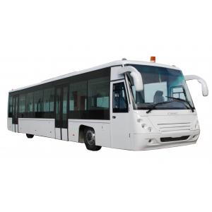
118kW 2300rpm Airport Apron Bus Xinfa Airport Equipment With Adjustable Seats
Contact Now
Add to Cart
Verified Supplier
Location:
Beijing Beijing China
Address:
No. 97 Changping Road, Shahe Town, Changping District, Beijing, P. R. China, 102206
Supplier`s last login times:
within 38 hours
Shipping
lt's easy to get a shipping quote! Just click the button below and complete the short form.
Get Shipping Quote
Product Details
Company Profile
Product Details
118kW 2300rpm Airport Apron Bus Xinfa Airport Equipment With Adjustable Seats
MAIN TECHNICAL PARAMETERS AND SPECIFICATIONS
AIRPORT APRON BUS
Aero ABus-5270
MAIN TECHNICAL PARAMETERS AND CONFIGURATIONS
AeroABus-5270
No. | Particulars | Specs | ||||
|---|---|---|---|---|---|---|
1. | Length × Width ×Height | 13650mm×2700mm×3178mm | ||||
2. | Bus body | Low carbon alloy steel body with aluminum apron; | ||||
3. | Wheel base | 6670mm | ||||
4. | Passenger accommodation capacity | Up to 77 passengers including thirteen (13) seats, in compliance with IATA specifications: four (4) Passengers per sqm | ||||
5. | Curb weight | 12250kgs | ||||
6. | The varied height from passenger cabin floor sill to the ground level | 270mm~340mm subject to embarkation and/or disembarkation of passengers | ||||
7. | Minimum turning radius | <13500mm | ||||
8. | Engine | 4-strok, diesel engine | ||||
Basic: DEUTZ BF4M1013-16E3, EUROIII, 118kW/2300rpm, ALLISON 2100 Option 1: DEUTZ BF4M1013-19E3, EUROIII, 140kW/2300rpm, ALLISON T270(with extra cost) Option 2: CUMMINS ISDE180-30, EUROIII, 132KW/2500rpm, ALLISON 2100 | ||||||
Normal rated power | 118kW | |||||
Rated speed | 2300 rpm | |||||
Discharge capacity | 4764cc | |||||
Compression ratio | 18.0 | |||||
Intake mode | Turbo-charging intercooler | |||||
Exhaust emission | EURO III | |||||
Fuel consumption | ≯215g/kwh Less than 30Liter per 100 km | |||||
Dry weight | 520kgs | |||||
Fire unit | Electromagnetic mechanism | |||||
Generator | 28Volt | |||||
Starter | 6 Kw, 24 Volt | |||||
9. | Battery | Battery (2 pcs): 190H52 Lead-acid battery | ||||
10. | Transmission (standard) | Allison 2100 automatic transmission, electronic controlled. | ||||
Velocity ratio | Gear | ALLISON 2100 | ALLISON T270 | |||
Gear 1 | 3.10 | 3.49 | ||||
Gear 2 | 1.81 | 1.86 | ||||
Gear 3 | 1.41 | 1.41 | ||||
Gear 4 | 1.00 | 1.00 | ||||
Reverse | 4.49 | 5.03 | ||||
11. | Volume capacity of vessels | Fuel tank volume | (120 + 80)liter | |||
Anti-freeze fluid | 20 liter | |||||
Engine lubrication system | 14.2 litter | |||||
Gearbox lubrication system | 18 liter | |||||
Main reduction gear of front axle and wheel rim reduction gear | 10 liter | |||||
Front brake | N/A | |||||
Steering gear | 5 liter | |||||
12. | Front axle (Driving axle) | MERCEDES BENZ 733.W14 (right-hand drive) MERCEDES BENZ 733.W02 (left-hand drive) | ||||
King-pin angle of toe-in | 5° | |||||
King-pin caster angle 0° | ||||||
Ratio of master drive: | 7.633 | |||||
Wheel rim velocity ratio | 1 | |||||
13. | Steering | SANHUAN, 3401ZB3-001H | ||||
14. | Rear axle | Specially manufactured high intensity curved axle | ||||
15. | Front tire (single tire) | BRIDGESTONE, 12R22.5 | ||||
16. | Rear tire (twins) | BRIDGESTONE, 9.5R17.5 | ||||
17. | Pneumatic suspension | GOODYEAR, 270~340mm, 6 nr. pneumatic suspension | ||||
18. | Seats |
| ||||
19. | Air conditioning in driver cabin | Model: THERMOKING S30, Cooling capacity: 8568Kcal/hour | ||||
20. | Air conditioning in passenger compartment | Model: THEMOKING KRS1139A Compressor: X430 Capacity: 36900Kcal/hour. | ||||
21. | Heating system for winter package (Option with extra cost) | Heater: Model: [YJP-Q30/XT ] 30kW, independent fuel heater Radiators: Model: [SR-4X/13 ] Power of motor: 100w Voltage: 24 Volt | ||||
22. | [NOT USED] | |||||
23. | Defroster in driver's cabin | Model: [CS-13/01] Motor: DC24V, 240W Heat output: 7.5KW (when water temp. at 80°C) | ||||
24. | Audio | Radio + CD + MP3 (2 Speakers in Driver’s cabin, 8 speakers in Passenger’s cabin) | ||||
25. | Intercom system |
| ||||
26. | IT Options (with extra costs) |
| ||||
27. | Passenger door system |
| ||||
28. | Driver cabin door |
| ||||
29. | Emergency system 1 |
| ||||
30. | Emergency system 2 |
| ||||
31. | Emergency system 3 | An emergency device for opening door is equipped on each door in the passenger cabin, when the device is activated, there is a voice alarm in the cabin; | ||||
32. | Windows in passenger cabin | Full size tempered glass panels mounted in the front and the back of passenger cabin. | ||||
33. | Rear air conditioning engine layout |
| ||||
34. | Painting system |
| ||||
35. | Warning signs |
| ||||
36. | Chassis |
| ||||
37. | Rainwater drainage gutter | Installed on upper part of bus body | ||||
38. | Parking sensor and monitor | Included | ||||
39 | Flooring | Anti-slip rubber floor | ||||
40. | Emergency button |
| ||||
41. | Roof positioning lights |
| ||||
42. | Fog lamps |
| ||||
43. | Side lights |
| ||||
44. | Warning lights | Front and rear yellow flashing warning lights are installed on the roof | ||||
45. | Interior Lighting |
| ||||
46. | Emergency escape |
| ||||
47. | Handrails and handgrip in bus |
| ||||
48. | Instructions in detail |
| ||||
49. | Assistance facilities for physical inconvenience passenger | One ramp for wheelchair is equipped in front door; Designated area is also allocated for wheel chairs. | ||||
50. | Others | Configured according to the standard in the Civil Aviation Association Development Corporation | ||||

118kW 2300rpm Airport Apron Bus Xinfa Airport Equipment With Adjustable Seats
Inquiry Cart
0