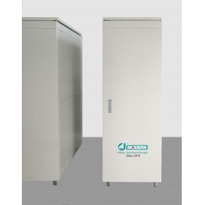
500KVA O R T E A Three Motors Auto Voltage Stabilizer AVS With Ourdoor IP44 Cabinet
Brand Name:Modern
Certification:CE,ISO9001
Model Number:SBW-F-500KVA
Minimum Order Quantity:1
Payment Terms:T/T
Place of Origin:China
Contact Now
Add to Cart
Verified Supplier
Location:
Wenzhou Zhejiang China
Address:
20 Jinsiqiao Road, Wenzhou, Zhejiang, China
Supplier`s last login times:
within 1 hours
Shipping
lt's easy to get a shipping quote! Just click the button below and complete the short form.
Get Shipping Quote
Product Details
Company Profile
Product Details
Wenzhou Modern Group is a leading company in the manufacture of Power Quality and Energy Saving Products in China.
Milestones:
- 1979: Founded as a manufacturer of transformer based power products
- 1988: Constant voltage transformer introduced and UL certified
- 1992: Became a strategic partner for GE Healthcare in China
- 1995: Obtained ISO9001 quality system
- 2003: Introduction of the patent variable transformer
- 2005: Became a strategy partner of Emerson Network Power
- 2010: Obtain CE for the voltage stabilizer
- 2013: Obtain CE for voltage optimization unit
Strict Quality Inspection:
Features:
1. Silent design with moving Long life roller carbon brushes, High reliability and low maintenance
2. Unique compact dimension.
3. Digital control.
4. Rich protection functions.
5. Efficiency up to 98%
6. Independent phase voltage regulation. Changeable through LCD
touchscreen display
on site.
7. Manual bypass, Automatic bypass (Optional)
8. Remote monitoring by RS485 or RS232 or WIFI, GPRS.
Main components :
Buck/boost transformer
Often referred to as 'booster' transformer, it is a standard dry-type transformer with the secondary winding connected in series to the mains and the primary winding supplied by the voltage regulator.
Voltage regulator
Basically, it is an autotransformer with continuously variable transformer ratio. The voltage intake varies depending on the position of the rolling contacts; therefore the voltage supplied to the booster transformer primary winding also varies. Being the voltage across the regulator contacts (and consequently that on the secondary winding of the booster transformer) either in phase or in opposition to the supply voltage, it is then added or subtracted to the supply voltage, thus compensating its variations.
Auxiliary circuit with a microprocessor
The DSP (Digital Signal Processor) microprocessor-based control
circuit (specifically designed for
drives with the totally digitalized signal) compares the output
voltage value to the reference one sampling it 2000 times per
second.
When an anomaly is detected, the controller drives the voltage
regulator gear motor. By doing so, the
regulator rollers change their position thus varying the voltage
drawn and supplied to the buck/boost
transformer primary winding. The input voltage variation is
therefore automatically compensated.
The control system operates so that the output accuracy is ±0.5%.
The microprocessor is fitted with the
soft stop function enabling a precise positioning of the regulator
rollers regulation to work smoothly
even in case of strong fluctuation of the input voltage.
Specifications:
| Input | |
| Rated voltage | 380V/400V/415V/460V |
| Input stable voltage range | 304V~456V |
| Working range | 240V~500V |
| Frequency | 50HZ/60HZ |
| Power Factor | ≥0.99 |
| Output | |
| Output voltage | 380V/400V/415V/460V |
| Max Current | 750A |
| Accuracy | 1% |
| Efficiency | ≥0.98% |
| Wave deformation | nil |
| Power Factor | 0.8~1 |
| Output protected | Under voltage:Vn-20%(Can be reset), Overvoltage: Vn+10%, Over Current: In*0.9 |
| Overload Capacity | 150%Over load 10seconds 120%Over Load 60seconds 110%Over Load 10minutes |
| General | |
| Technology | Digital Signal Processing(DSP) And Voltage vector control Technology |
| Method of voltage regulation | Three phase independent regulation with long life roller brush drive by three servo motors |
| Correction time | Step up or step down 10% of rated voltage from the input voltage, The output will stable to rated voltage after 2 seconds |
| Safe start | The AVR will start output after 6 seconds delay |
| Insulation class | H & C class(180℃ & 220℃) |
| Insulation resistance | ≥5MΩ |
| Cooling System | Auto Forced Air |
| Wire system | 3-phase-5-wire-system & 3-phase-4-wire-system without neutral |
| Protection class | IP44(Outdoor) |
HOW TO CHOOSE A VOLTAGE STABILIZER?
What's the difference between Roller carbon brush with the Flat carbon brush?
Comparative of the different of Voltage stabilizer:
| Servo with the roller brush and columnar transformer | Servo with the flat brush and columnar transformer | Servo with the flat brush and Flat transformer | Induction AVR with Oil cooling | Electric AVR | Static AVR | |
|---|---|---|---|---|---|---|
| Typical efficiency | ≥98% | ≥97% | ≥95% | 80%~90% | ≥90% | ≥98% |
| Power factor | 0.99 | 0.99 | 0.85~0.95 | 0.8~0.9 | 0.85~0.9 | 0.8 |
| Correction speed | 1s | 1s | 1s | Slow, 1 Min | 0.05s | 0.1s |
| Reliability | High | Middle | Low | High | Middle | Middle |
| Weight | Middle | Heavy | small | Very heavy | small | smaller |
| Dimension | small | Large | Middle | Huge | smaller | smallest |
| Noise | Silent with No Noise | Noise when Voltage regulated | Noise when Voltage regulated | Continuous Noise | Cooling Fan's Noise | Cooling Fan's Noise |
| Maintenance | Clean the dust once per 6 months | Clean the dust once per 6 months | Clean the dust once per 6 months | Complicated due to Oil | Clean the dust once per 6 months | Clean the dust once per 6 months |
| Application | All kinds load | All kinds loads | Family | Industrial | Residential Load | Residential Load |
| Install | Anywhere | Anywhere | Anywhere | Outdoor Only | Anywhere | Anywhere |
| Environmental | Clean | Clean | Clean | Polluted | Clean | Clean |
What's the difference of stable range and working range?
How to choose the capacity of the voltage stabilizer:
Principles
The voltage stabilizer and the voltage regulator are chosen according to the current:
1 Continuous working current is smaller than the rated current of the voltage stabilizer or voltage regulator, Better to have a design margin of 20%.
2 The loads start current is smaller than 5 times of rated current of the servo voltage stabilizer with the roller brush and columnar transformer. or 2.5 times the servo voltage stabilizer with a flat brush, 2 times the static voltage stabilizer.
How to choose the capacity of the voltage stabilizer:
Loads Rated current:
Single phase:
Rated current In=Pn/(Vn*cosφ)
Three phase:
Rated current In= Pn/(1.732*Vn*cosφ)
Note:
Pn — Load capacity(kW),
Vn — Rated voltage(V), Tt is Line to Line voltage in three phase system
Cosφ — Power factor.
How to choose the capacity of the voltage stabilizer:
Loads surge current:
Three phase(Motors):
1 Direct start: I(tmax)= In total + In(max)*6
2 Autotransformer start: I(tmax)= In total + In(max)*3
3 Star-Delta start: I(tmax)= In total + In(max)*3
4 Variable Frequency start: I(tmax)= In total + In(max)*2
5 Soft start: I(tmax)= In total + In(max)*3
Note:
I(tmax)— The max start current.
In total — The total rated currents of the loads
In(max)— The max starting current of the motor.

500KVA O R T E A Three Motors Auto Voltage Stabilizer AVS With Ourdoor IP44 Cabinet
Inquiry Cart
0