High Speed Micro - Stepping Two - Phase Hybrid Stepper Motor Drivers CW-1108
Brand Name:Smart Automation
Certification:CE, RoHs
Model Number:CW-1108
Minimum Order Quantity:5
Delivery Time:2~4 weeks
Payment Terms:bank TT
Contact Now
Add to Cart
Active Member
Location:
Changzhou Jiangsu China
Address:
No.20 Guanghua Street, Changzhou, Jiangsu, China 213003
Supplier`s last login times:
within 1 hours
Shipping
lt's easy to get a shipping quote! Just click the button below and complete the short form.
Get Shipping Quote
Product Details
Company Profile
Product Details
High Speed Micro - Stepping Two - Phase Hybrid Stepper Motor Drivers CW-1108
Note: please read the instruction book carefully before installing
the driver
I Performance and features
- Microstepping control: step motor can be operated and located for 1,1/2,1/4……1/256,1/5,1/10……1/50 origin step angle, so the control accuracy is increased and the defect of rough running and easy to out-of-step operation in low speed is overcome.
- Smooth-subdivision control: minimum positioning accuracy is still the origin step angle of motor, but smooth-subdivision transition is used between steps to overcome the defect of rough running and easy to out-of-step operation in low speed.
- High speed and high torque: the slaving voltage of power amplifier is DC140V, so high-torque output is obtained in high speed.
- New technique: control core consists of Single Chip Microcomputer and programmable array, good control performance; large power IGBT amplifier tube made by Fairchild Co. in USA, strong overload and overheat ability, hard to burnout.
- High reliability: high integrated level of control circuit, few connecting lines, dust-proof structure, protection of over temperature, over current and under voltage.
II Technical data Power input: AC110V/5A
Adapted motor:110~130 series two-phase hybrid stepping motor
Step angle subdivision: 1:1, 1:2……,1:10,1:20 Look the table
Input signal: impulse (CP)direction (CW), enable (FREE)
Signal level:5V,3~15mA, 1K resistance series in 12V, 2K resistance
series in 24V
Maximum input pulse frequency: 50K
Minimum input pulse width: 10uS
III Interface and dial switch (DIP)
1. Tables of InterfacesSaignal interface table
PIN | Terminal name | Description |
1 | CP+ | Pulse (+) Input |
2 | CP- | Pulse (-) Input |
3 | DIR+ | Direction (+)Input |
4 | DIR- | Direction (-)Input |
5 | FREE+ | Power down (+) Input |
6 | FREE- | Power down (-) Input |
Motor interface table:
Terminal name | Description |
A | head of phase A |
A | end of phase A |
B | head of phase B |
B | end of phase B |
power interface table:
Terminal name | Description |
AC | AC110input |
AC | AC110 input |
PE | Power Grand |
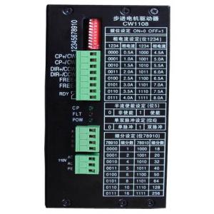
2 Setting of dial switch
Setting current
switch:ON=0,OFF=1 | ||||||||||||||||
1 | 0 | 0 | 0 | 0 | 0 | 0 | 0 | 0 | 1 | 1 | 1 | 1 | 1 | 1 | 1 | 1 |
2 | 0 | 0 | 0 | 0 | 1 | 1 | 1 | 1 | 0 | 0 | 0 | 0 | 1 | 1 | 1 | 1 |
3 | 0 | 0 | 1 | 1 | 0 | 0 | 1 | 1 | 0 | 0 | 1 | 1 | 0 | 0 | 1 | 1 |
4 | 0 | 1 | 0 | 1 | 0 | 1 | 0 | 1 | 0 | 1 | 0 | 1 | 0 | 1 | 0 | 1 |
current(A) | 0.5 | 1.0 | 1.5 | 2.0 | 2.5 | 3.0 | 3.5 | 4.0 | 4.5 | 5.0 | 5.5 | 6.0 | 6.5 | 7.0 | 7.5 | 8.0 |
MicrosteppingSetting
switch:ON=0,OFF=1 | ||||||||||||||||
7 | 0 | 0 | 0 | 0 | 0 | 0 | 0 | 0 | 1 | 1 | 1 | 1 | 1 | 1 | 1 | 1 |
8 | 0 | 0 | 0 | 0 | 1 | 1 | 1 | 1 | 0 | 0 | 0 | 0 | 1 | 1 | 1 | 1 |
9 | 0 | 0 | 1 | 1 | 0 | 0 | 1 | 1 | 0 | 0 | 1 | 1 | 0 | 0 | 1 | 1 |
10 | 0 | 1 | 0 | 1 | 0 | 1 | 0 | 1 | 0 | 1 | 0 | 1 | 0 | 1 | 0 | 1 |
micro | 1 | 2 | 4 | 5 | 6 | 8 | 10 | 16 | 18 | 20 | 32 | 40 | 50 | 64 | 128 | 256 |
Switch6:
double pulse or single pulse Setting.
"ON”=0----single pulse;
”OFF”=1-------double pulse
Switch5:
the half current enable.
”ON”=0------unable;
”OFF”=1-----enable
IV Schematic diagram of interfaces
double pulse or single pulse Setting.
"ON”=0----single pulse;
”OFF”=1-------double pulse
Switch5:
the half current enable.
”ON”=0------unable;
”OFF”=1-----enable
IV Schematic diagram of interfaces
V Installation
1. Open and check
CW1108 driver is enclosed with plastic connectors, please open the
box and check the connectors, If not coincidental, please contact
us for settlement immediately.
2. Installation
Microstepping Motor Driver CW-1108
3. Wiring
Please connect wires according to interfere table and schematic
diagram of interfaces. The sectional area of power wire and motor
wire should be greater than1 square millimeter. Make sure that
wiring joint is firm. Prevent joint from heating to destroy parts
and cause driver work abnormally, and attention good ground
connection.
VI Fault detection
When the system has fault, how do we confirm that it aroused by the
driver or not? “Substitution method” can do it. This means that a
new driver substitutes a “bad” one. After the substitution, if the
system returns to normal condition, it is identified that the
driver is bad. Otherwise, other parts but the driver should be
checked. But, the following cases are not caused by bad driver,
please note:
Insulating transformer
Fault case | Fault cause |
Having power amplification, But the electromotor can’t run | No CP, signal input or its polarity reverse. |
Electromotor can only run to one way | Wrong U/D input: |
The electromotor can work normally, but it may lose steps. | (1) The controller control rise and drop is too fast. |
Note: As to lose step because of resonance, adjusting the damping
disk in back cover of the electromotor can solve it. If the driver
is damaged, please contact manufacturer for repair

High Speed Micro - Stepping Two - Phase Hybrid Stepper Motor Drivers CW-1108
Inquiry Cart
0